Installation – Tripp Lite XL User Manual
Page 5
15
2-4
A
B
C
D
15
2-5
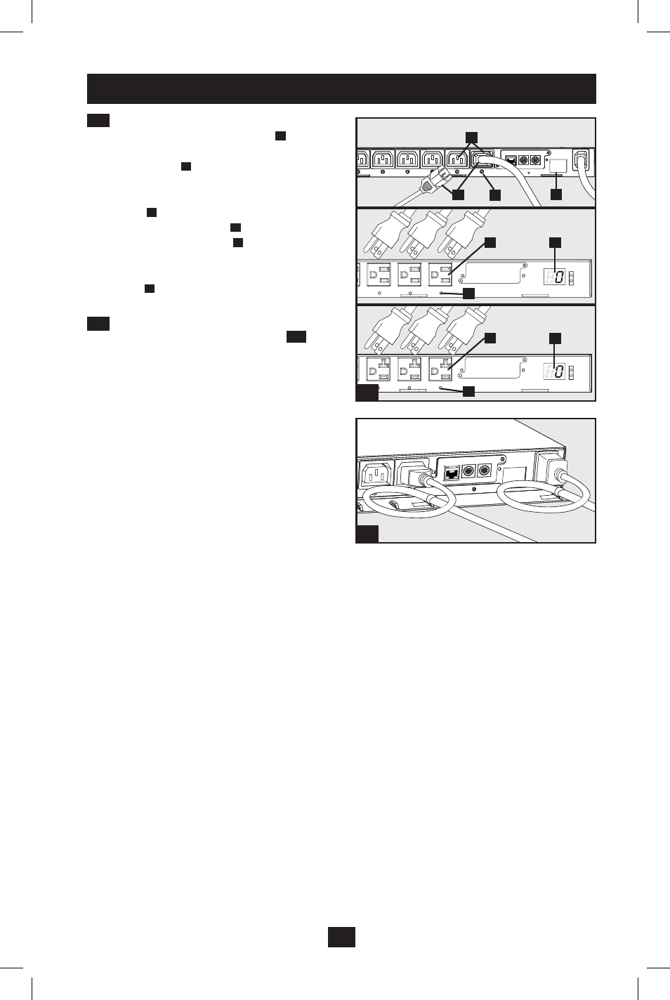
PDUMH20NET
PDUMH15NET
PDUMH15HVNET/PDUMH20HVNET
B
B
D
D
C
C
5
Installation
continued
2-4
Equipment Power Cord Connection:
Insert the IEC 60320 C14 connectors
A
of the
equipment power cords into the IEC 60320 C13
output receptacles
B
of the PDU
(PDUMH15HVNET and PDUMH20HVNET).
Insert power cords into the NEMA 5-15R output
receptacles
B
(PDUMH15NET) or NEMA
5-15/20R output receptacles
B
(PDUMH20NET). The LED
C
near each output
receptacle illuminates when the receptacle is
ready to distribute live AC power. The digital
load meter
D
will display the total connected
equipment load in amps.
2-5
Cord Retention (Optional): If you
attached the cord retention shelf in step
1-6
, tie
the input power cord and each equipment power
cord to the retention shelf. Attach each cord to
the retention shelf by looping the cord and
securing it to an attachment point with one of
the included cable ties. Make sure that each cord
can be unplugged from the PDU without
removing the cable tie.
201110149-93-2718.indd 5
11/9/2011 11:17:31 AM