Installation low voltage wiring – Trane GETB User Manual
Page 16
16
WSHP-SVN08B-EN
Low Voltage Wiring
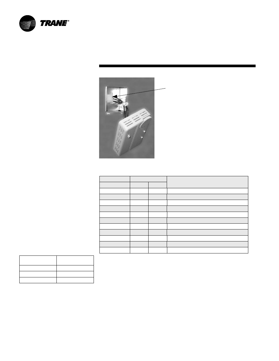
Factory ordered thermostats and zone
sensors are pre-wired with a quick
connecting plug.
1 After installing the cabinet assem-
bly, simply plug the male portion of
thermostat/zone sensor plug into
the female portion of the plug locat-
ed inside the unit’s junction box.
2 Mount the thermostat or zone sen-
sor on the finished drywall.
Thermostat/zone sensor connection is
shown in Figure 13.
Low Voltage Wiring for Field
Provided Thermostats/Zone
Sensors
Ensure that the AC control wiring be-
tween the controls and the unit’s ter-
mination point does not exceed three
(3) ohms/conductor for the length of
the run.
Note: Resistance in excess of 3-ohms
per conductor may cause component
failure due to insufficient AC voltage
supply.
Check all loads and conductors for
grounds, shorts, and mis-wiring.
Use copper conductors unless other-
wise specified.
Do not run the AC low voltage wiring
in the same conduit with the high volt-
age power wiring.
Table 4: 24V AC conductors
Distance from unit
to Control
Recommended
Wire Size
000-460 feet
18 gauge
461-732 feet
16 gauge
733-1000 feet
14 gauge
Installation
Low Voltage Wiring
Table 5: Deluxe controller diagnostic LEDs
Color: Green
Color: Red
Controller Mode
LED1
LED2
LED3
OFF
OFF
OFF
Control OFF
ON
OFF
OFF
Normal/Compressor OFF
ON
OFF
FLASH
Anti-short Cycle
ON
OFF
ON
Normal/Compressor ON
FLASH
ON
OFF
Brownout Condition
ON
FLASH
ON
Soft Lockout (low pressure)
ON
FLASH
FLASH
Soft Lockout (high pressure)
ON
ON
ON
Manual Lockout (low pressure)
ON
ON
FLASH
Manual Lockout (high pressure)
ON
FLASH
OFF
Manual Lockout (condensate overflow)
ON
ON
OFF
Compressor Disable
Factory provided plug
Six (6) Pin Connector/Harness
Red = 24V
Black = Fan
Orange = RV
Yellow = Compressor
Blue = Common
Figure 13: Zone sensor connection