Installation, Warning, Live electrical components – Trane GETB User Manual
Page 14
14
WSHP-SVN08B-EN
WARNING
Live Electrical
Components!
During installation, testing, ser-
vicing and troubleshooting of this
product, it may be necessary to
work with live electrical compo-
nents. Have a qualified licensed
electrician or other individual
who has been properly trained in
handling live electrical compo-
nents perform these tasks. Failure
to follow all electrical safety pre-
cautions when exposed to live
electrical components could re-
sult in death or serious injury.
7 Flush system. See Cleaning and
Flushing the Water Loop for flushing
instructions.
8 Open the unit water valves and
check piping for leaks.
9 Connect electrical to unit chassis via
the quick connect mating plugs.
Note: Four plugs are included (motor,
optional condensate overflow, power
and thermostat).
10 Slide chassis into the cabinet. Cen-
ter the chassis left to right to mini-
mize sound transmission. See
Figure 11.
Figure 11: Install chassis centered
11 Verify unit’s air filter is properly
place in the chassis filter rack.
12 Install cabinet’s front cover to the
hinged door.
IMPORTANT
Ensure the gasket material creates a
positive seal around the entire coil to
avoid coil bypass.
If a field supplied door is used, ensure
the front cover is attached to the build-
ing structure and not the unit cabinet.
Supply Grille installation
See Table 2 for supply air dimensions.
1
Install the supply grille(s) into the
cabinet discharge opening. Insure
there are no air gaps between the
cabinet supply air and the grille.
This helps prevent recirculation of
supply air into the return air open-
ing behind the drywall.
2
Secure grille(s) into the drywall via
two screws.
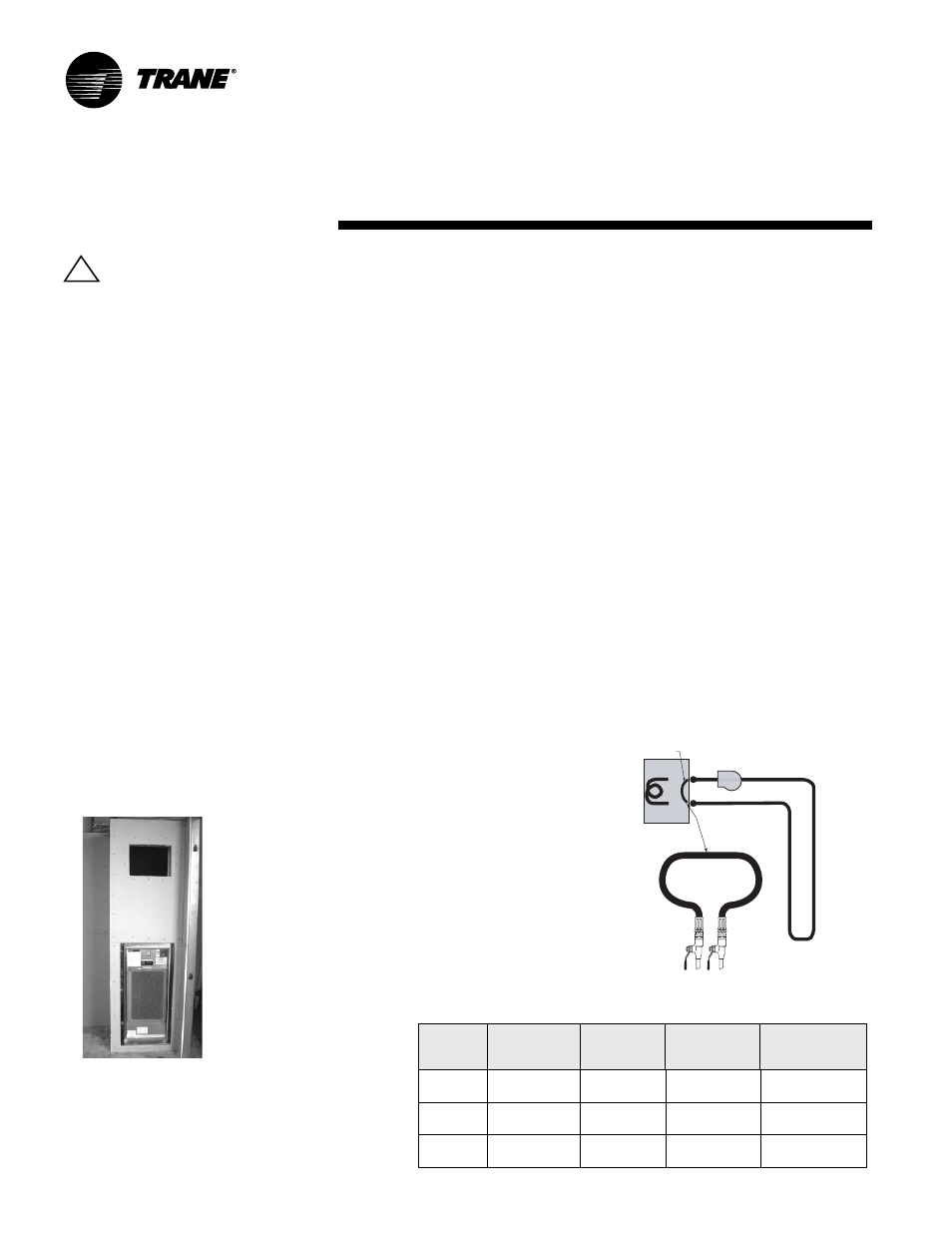
Cleaning and Flushing
the Water Loop
After the piping system is complete,
the flexible hose connectors should be
doubled back to complete the water
circuit external to the unit (avoiding
trash settle-out in the condenser). An
extra pipe may be necessary to con-
nect the hose kits. See Page 15 for an-
tifreeze/water mixture by volume.
3 Water circulation system should be
filled with clean water using the wa-
ter make up connections. Note: Air
vents should be opened during fill-
ing.
4 With the air vents closed, start the
circulating pump and then crack the
air vents to bleed off the trapped
air, assuring circulation through all
components of the system.
Note: Make up water must be available
to the system to replace the volume
formerly occupied by the air that is
bled off.
5 With the air vented and the water
circulating, the entire system
should be checked for leaks with re-
pairs made as required.
6 Operate the supplementary heat
system making checks per manu-
facturer’s instructions. During this
operation, visual checks should be
made for leaks that may have oc-
curred due to increased heat. Re-
pair as required.
7 Open the system at the lowest point
for the initial blow down (making
sure the make up water is equal to
the water being dumped). Continue
blow down until the water leaving
the drain runs clear, but not less
than 2 hours.
8 Shut down pumps and supplemen-
tary heat system. Reconnect the
hoses placing the water-to-refriger-
ant heat exchanger in the water cir-
culating system.
Note: Vents should be open when the
pumps and supplementary heat sys-
tem are shut down.
Figure 12: Flushing the water loop
Table 2: Supply air opening size
GET
Model
Single Grille
100% CFM
Two Grille
50% CFM
Three Grille
33% CFM
Top Discharge
Up to 100%
CFM
009, 012
12W x 10H
(305 x 254)
10W x 6H
(254 x 152)
Not
Recommended
14 x 10
(356 x 254)
015, 018,
024
14W x 12H
(356 x 305)
14W x 12H
(356 x 305)
12W x 8H
(305 x 203)
16 x 14
(406 x 356)
036
Not
Recommended
16W x 14H
(406 x 356)
14W x 12H
(356 x 305)
17 x 17
(432 x 432)
CIRCULATING
PUMP
WATER-SOURCE
HEAT PUMP
CONNECTION
HOSE
GROUND-LOOP
OR
COOLING TOWER/BOILER
TEMPORARY
CONNECTION
FOR SYSTEM
FLUSHING
Installation
!