Audio, 2 audio – TANDBERG 7000 MXP User Manual
Page 213
Peripheral Equipment
213
It is possible to extend existing DVI cables by the use of extension cables. The maximum cable
length however, is 5 meters. Going beyond that may result in quality loss.
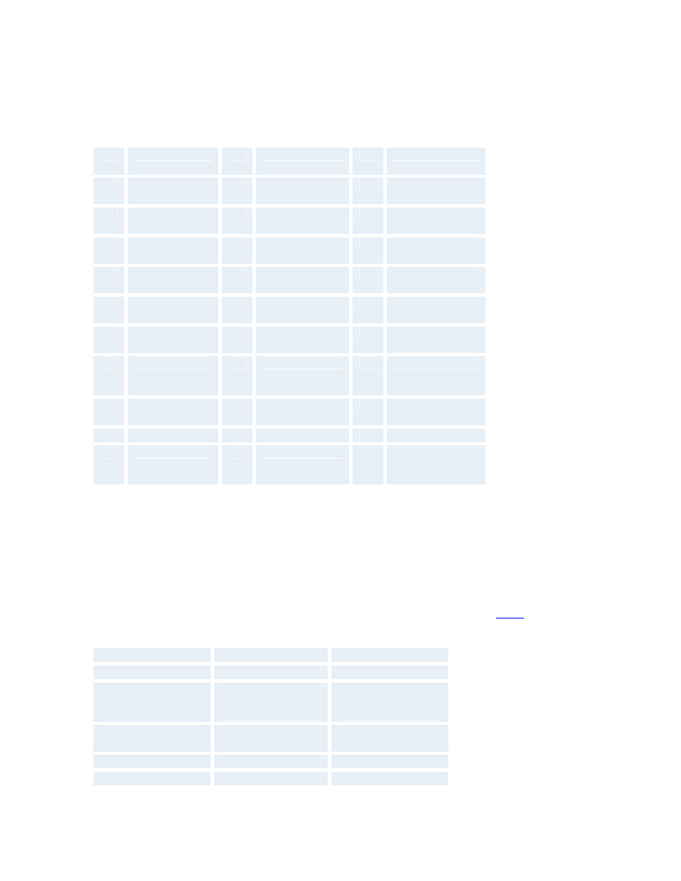
DVI-I - Combined Analog and Digital Connector Pin Assignments:
Pin
Signal
Assignment
Pin
Signal
Assignment
Pin
Signal
Assignment
1
T.M.D.S.
Data2-
9
T.M.D.S.
Data1-
17
T.M.D.S. Data0-
2
T.M.D.S.
Data2+
10
T.M.D.S.
Data1+
18
T.M.D.S. Data0+
3
T.M.D.S.
Data2/4 Shield
11
T.M.D.S.
Data1/3 Shield
19
T.M.D.S.
Data0/5 Shield
4
T.M.D.S.
Data4-
12
T.M.D.S.
Data3-
20
T.M.D.S. Data5-
5
T.M.D.S.
Data4+
13
T.M.D.S.
Data3+
21
T.M.D.S. Data5+
6
DDC Clock
14
+5V Power
22
T.M.D.S. Clock
Shield
7
DDC Data
15
Ground (return
for +5V, HSync
and VSync)
23
T.M.D.S. Clock+
8
Analog Vertical
Sync
16
Hot Plug Detect
24
T.M.D.S. Clock-
C1
Analog Red
C2
Analog Green
C3
Analog Blue
C4
Analog
Horizontal
Sync
C5
Analog Ground
(analog, R, G &
B return)
5.1.2 Audio
6 Audio Inputs:
3 microphone inputs (balanced, 24V phantom powered) via XLR connectors.
3 audio inputs (line level) via RCA connectors.
All audio inputs are active by default. For further information, refer to chapter 4.5
Audio input connector specification:
Connector label
Microphone(s)
Audio input(s)
Signal type
Balanced
Unbalanced
Connector (codec)
XLR-F, pin 1-gnd,
pin 2 hot, pin 3-
cold/neutral
Female RCA/phono,
sleeve-ground,
centre-signal
Input impedance
2400 ohms (pin 2 -
3)
10K ohms
Maximum input level
83 mVpp
15.5 Vpp
Minimum input level
6.2 mVpp
1.17 Vpp