Rear panel sockets overview, Codec c90 system integrator guide – TANDBERG Codec C90 D14128.02 User Manual
Page 17
D14128.02—NOVEMBER 2008
17
Codec C90
System Integrator Guide
Contents
Introduction
Getting Started
Interfaces
About the API
xConfiguration
xCommand
xStatus
Cameras
Appendices
Contact us
Interfaces
Codec C90 Rear Panel
Audio sockets
Video sockets
Network
interface
sockets
Power
socket
Power
switch
COM Port,
Camera
Control
Audio sockets
Video sockets
GPIO and USB
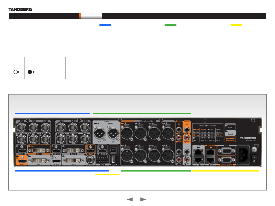
Rear panel sockets
overview
The TANDBERG Codec C90 offers a great flexibility
in connecting audio and video equipment to the
system.
The illustration below shows the rear panel of the
TANDBERG Codec C90.
Video sockets
The video input sockets are:
4 x HDMI
4 x HD-SDI
2 x DVI-I
2 x Analog Component (Y-Pr-Pb)
1 x Composite* or 1 x S-Video(YC)*
The video output sockets are:
2 x HDMI
2 x DVI-I
1 Composite
Audio sockets
The audio input sockets are:
8 x XLR Female - Microphone/Line In
4 x RCA - Line In (1 Left, 2 Right, 3 Left, 4 Right)
2 x HDMI
The audio output sockets are:
2 x XLR Male - Line Out
4 x RCA - 1 Left (SPDIF), 2 Right, 3 Left
(SPDIF), 4 Right
2 x HDMI
Other sockets
The other sockets are:
Ethernet 1 and Ethernet 2*
COM - Serial data port
Camera control - Serial port for camera control
Power socket
Grounding - Chassis grounding
Power On/Off switch
GPIO**, USB Host**, USB Device**, T Link**
The following pages gives a detailed description of the rear panel sockets and connectors.
Inputs
Outputs
TANDBERG Basic
Setup
1
1
The main connectors
for TANDBERG basic
setup are highlighted
in
orange
.
* Not supported in version 1
** For future use
T Link