Block diagram for supported cameras, 3 block diagram for supported cameras – Telit Wireless Solutions GE863-QUAD User Manual
Page 64
GE863-QUAD
GE863-PY
1vv0300715 Rev. 1 - 19/09/06
Reproduction forbidden without Telit Communications S.p.A. written authorization - All Right reserved
page 64 of 79
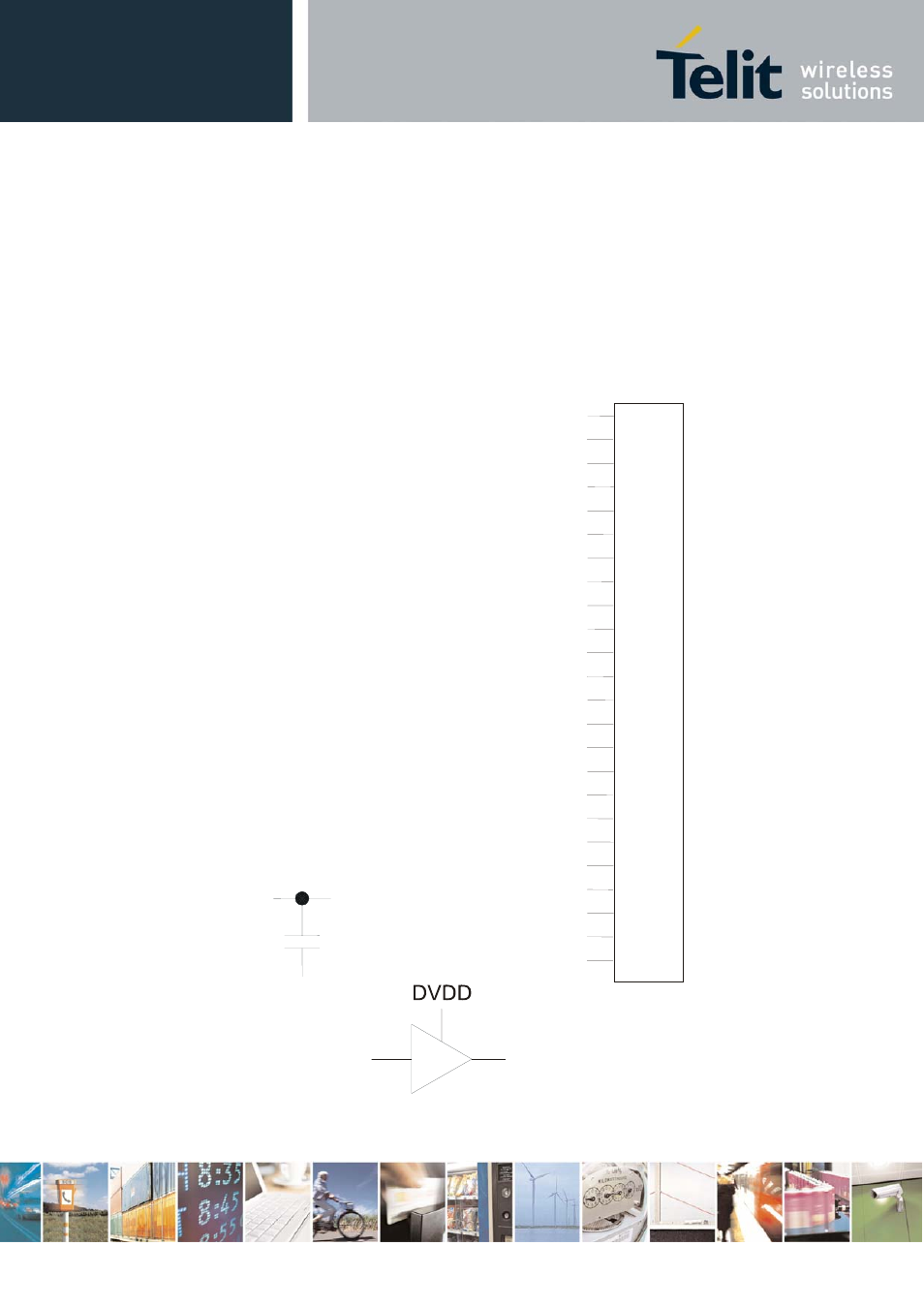
12.1.3
Block Diagram for supported cameras
The numbers on the left side of the Camera’s connectors refers to Module Connector’s pin number.
DVDD is VAUX1 power supply from GE863-QUAD / PY
1
2
3
4
5
6
7
8
9
10
11
12
13
14
15
16
17
18
19
20
21
22
23
24
GND
AVDD
CAM_CLK
GND
DVDD
IICSDA_CAM
GND
GND
PD[1]
PD[0]
PD[6]
CAM_CLK
DVDD
AVDD
GND
CAMERA TRANSCHIP
MON1_CAM
This manual is related to the following products: