Cor (carrier operated relay) i/o (input/output), Ptt connection, Monitor connection – Telex IP-223 User Manual
Page 26: R1 and r2 relays, Cor (c, Arrier, Perated, Elay, Ptt c, Onnection
Installation and Level Settings
28
NOTE:
When the speaker output is used, the radio volume control affects the audio levels of the IP-223.
COR (Carrier Operated Relay) I/O (Input/Output)
The COR I/O connection indicates that audio is being received from the radio. The COR connection is provided at DIG6, pin
20 of the DB25 connector.
PTT Connection
Connect the radio PTT circuit to the PTT relay contact terminals on the DB25 connector. Usually the common of the relay
contact switch is grounded and the normally open contact connects to the PTT input. An alternative method to ground the
common of the relay internal to the unit is to jumper R377 (line 1) and R381 (line 2) with a piece of wire soldered closed.
Monitor Connection
Connect the radio MON circuit to the MON relay contact terminals on the DB25 connector. Usually the common of each relay
contact switch is grounded and the normally open contact connects to the MON input. An alternative method to ground the
common of the relay internal to the unit is to jumper R376 (line 1) and R380 (line 2) with a piece of wire soldered closed.
R1 and R2 Relays
The IP-223 provides two (2) relay closures for controlling the frequency of the radio, or switching a remote ancillary device.
The F1 and F2 contacts can be connected through the DB25 connector. Usually the common of each relay contact switch is
grounded and the normally open contact connects to the radio frequency control terminals. Information on programming the
R1 and R2 relays is provided in the “Setup Information” chapter of this manual starting on page 33. An alternative method to
ground the common of the relay R1 internal to the unit is to jumper R375 (line 1) and R379 (line 2), and for relay R2 jumper
R374 (line 1) and R378 (line 2) with a piece of wire soldered closed.
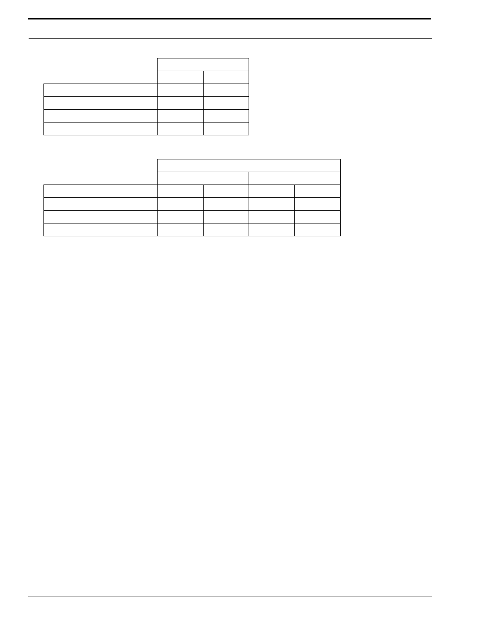
Jumper Position
Line 1
Line 2
Receive Input Impedance:
J14
J24
8 ohms (for a speaker input)
B
B
600 ohm
A
A
10k ohm
NULL
NULL
Jumper Position
Line 1
Line 2
Receive Input Impedance:
J14
J23
J17
J24
8 ohms (for a speaker input)
B
A
A
B
600 ohm
A
B
B
A
10k ohm
B
B
B
B