Chapter 3 installation and level settings, Local/radio connections, Jumper positions – Telex IP-223 User Manual
Page 23: Installation and level settings . 25, Umper, Ositions, Figure 7. jumper positions, Installation and level settings
25
CHAPTER 3
Installation and Level Settings
Local/Radio Connections
NOTE:
Connections to radios differ from connections for remote operation; therefore connections are discussed
separately.
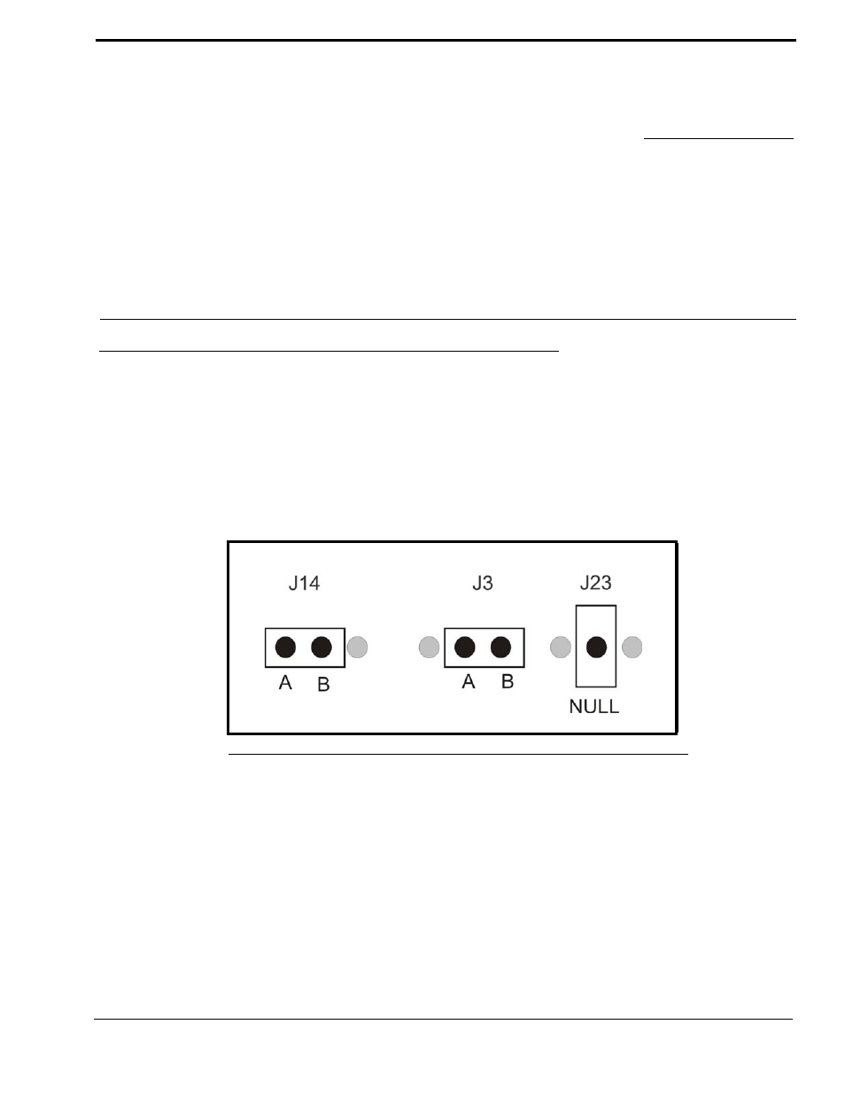
Jumper Positions
An example of the jumper positions are shown in Figure 82. In the figure, jumper 14 (J14) is shown in position A, jumper 3
(J3) is shown in position B, and jumper 23 (J23) has been placed on the center pin indicating the jumper is in the NULL
position.
To adjust the position of a jumper, do the following:
1.
Remove power from the IP-223 unit.
CAUTION: Failure to remove power may cause damage to the IP-223.
2.
Remove the six (6) screws from the case top.
FIGURE 82.
Jumper Positions