Vi/ii speed, Frequency setpoint #1 on pg. 134, Vi/ii speed frequency setpoint #1 on pg. 134 – Toshiba W7 User Manual
Page 140: V/f pattern, Vi/ii speed frequency setpoint #1, Vector motor model slip frequency gain
134
W7 ASD Installation and Operation Manual
Vector Motor Model Slip Frequency Gain
Program
⇒
Motor Settings
⇒
Vector Motor Model Slip Frequency
Gain
This parameter provides a degree of slip compensation for a given load. A
higher setting here decreases the slip allowed for a given load/ASD output ratio.
Parameter Type — Numerical
Factory Default — 0.60
Changeable During Run — Yes
Minimum — 0.00
Maximum — 2.55
V/f Pattern
Program
⇒
Fundamental Parameters
⇒
Fundamental #1
⇒
V/f Pattern
This function establishes the relationship between the output frequency and the
output voltage.
Settings:
Constant Torque
Variable Torque
Parameter Type — Selection List
Factory Default — Variable Torque
Changeable During Run — No
VI/II Speed Frequency Setpoint #1
Program
⇒
Frequency Settings
⇒
Speed Reference Setpoints
⇒
VI/II
⇒
VI/II Speed Frequency Setpoint #1
This parameter is used to set the gain and bias of the VI/II input terminal when
the VI/II terminal is used as the control input while operating in the Speed
Control mode.
Note: See note on
for further information on the VI/II
terminal.
VI/II Input Speed Control Setup
Perform the following setup to allow the system to receive Speed control input
at the VI/II input terminal:
• Program
⇒
Utilities ⇒ Command and Frequency Settings ⇒ Command
Mode Select
⇒
Terminal Block.
• Program
⇒
Utilities ⇒ Command and Frequency Settings ⇒ Frequency#1
Mode Select
⇒
VI/II.
• Provide a Run command (F and/or R).
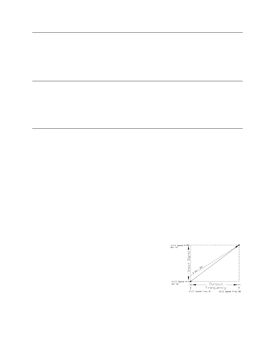
Speed Control
Perform the following setup to allow the system to perform Speed control from
the VI/II input terminal:
• Set VI/II Speed Frequency #1,
• Set the VI/II input signal level (VI/II Speed Ref #1) that represents VI/II
Speed Frequency #1,
• Set
VI/II Speed Frequency Setpoint #2
, and
• Set the VI/II input signal level (VI/II Speed Ref #2) that represents
Once set, as the VI input voltage or the II current changes, the output frequency
of the ASD will vary in accordance with the above settings.
This parameter sets VI/II Speed Frequency #1 and is the frequency that is
associated with the setting of
VI/II Speed Reference Setpoint #1
when
operating in the Speed Control mode.
Parameter Type — Numerical
Factory Default — 0.0
Changeable During Run — Yes
Minimum — 0.0
Maximum — Max. Freq.
Units — Hz
Frequency Settings