Texas Instruments TPA3008D2 User Manual
Page 6
www.ti.com
TPA3008D2
SLOS435A – MAY 2004 – REVISED JULY 2004
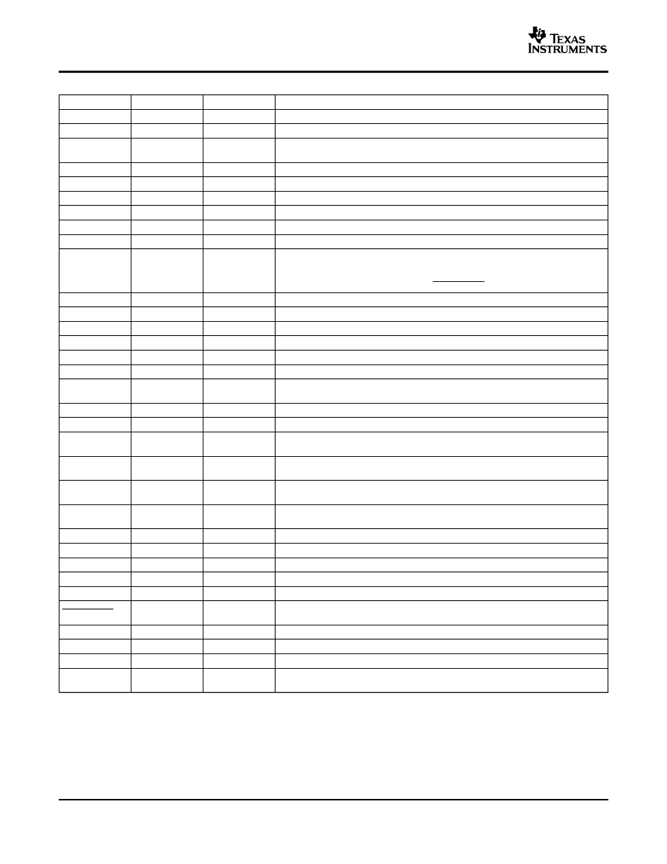
TERMINAL FUNCTIONS
PIN NAME
PIN NUMBER
I/O
DESCRIPTION
AGND
26, 30
-
Analog ground for digital/analog cells in core
AV
CC
33
-
High-voltage analog power supply, not connected internally to PVCCR or PVCCL
5-V Regulated output for use by internal cells and GAIN0, GAIN1 pins only. Not
AV
DD
29
O
specified for driving other external circuitry.
AV
DD
REF
7
O
5-V Reference output—connect to gain setting resistor or directly to GAIN0, GAIN1.
BSLN
13
-
Bootstrap I/O for left channel, negative high-side FET
BSLP
24
-
Bootstrap I/O for left channel, positive high-side FET
BSRN
48
-
Bootstrap I/O for right channel, negative high-side FET
BSRP
37
-
Bootstrap I/O for right channel, positive high-side FET
COSC
28
I/O
I/O for charge/discharging currents onto capacitor for ramp generator.
Short-circuit detect fault output.
FAULT = high, short-circuit detected.
FAULT
11
O
FAULT = low, normal operation.
Status is reset when power is cycled or SHUTDOWN is cycled.
GAIN0
9
I
Gain select least significant bit. TTL logic levels with compliance to AV
DD
.
GAIN1
10
I
Gain select most significant bit. TTL logic levels with compliance to AV
DD
.
LINN
6
I
Negative audio input for left channel
LINP
5
I
Positive audio input for left channel
LOUTN
16, 17
O
Class-D 1/2-H-bridge negative output for left channel
LOUTP
20, 21
O
Class-D 1/2-H-bridge positive output for left channel
8, 12, 31, 32,
NC
-
No internal connection
34, 35
PGNDL
18, 19
-
Power ground for left channel H-bridge
PGNDR
42, 43
-
Power ground for right channel H-bridge
Power supply for left channel H-bridge (internally connected to pins 22 and 23), not
PVCCL
14, 15
-
connected to PVCCR or AV
CC
.
Power supply for left channel H-bridge (internally connected to pins 14 and 15), not
PVCCL
22, 23
-
connected to PVCCR or AV
CC
.
Power supply for right channel H-bridge (internally connected to pins 46 and 47),
PVCCR
38, 39
-
not connected to PVCCL or AV
CC
.
Power supply for right channel H-bridge (internally connected to pins 38 and 39),
PVCCR
46, 47
-
not connected to PVCCL or AV
CC
.
RINP
3
I
Positive audio input for right channel
RINN
2
I
Negative audio input for right channel
ROSC
27
I/O
I/O current setting resistor for ramp generator.
ROUTN
44, 45
O
Class-D 1/2-H-bridge negative output for right channel
ROUTP
40, 41
O
Class-D 1/2-H-bridge positive output for right channel
Shutdown signal for IC (low = shutdown, high = operational). TTL logic levels with
SHUTDOWN
1
I
compliance to V
CC
.
VCLAMPL
25
-
Internally generated voltage supply for left channel bootstrap capacitors.
VCLAMPR
36
-
Internally generated voltage supply for right channel bootstrap capacitors.
V2P5
4
O
2.5-V Reference for analog cells.
Connect to AGND and PGND—should be the center point for both grounds. Internal
Thermal Pad
-
-
resistive connection to AGND.
6