Differential input and btl output – Texas Instruments TPA3008D2 User Manual
Page 21
www.ti.com
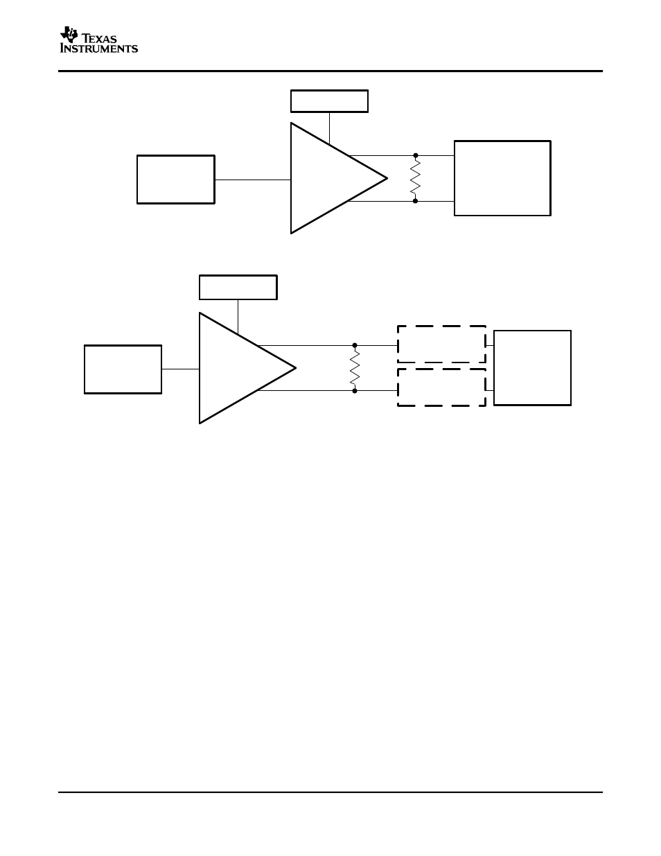
Analyzer
20 Hz − 20 kHz
(a) Basic Class−AB
APA
Signal
Generator
Power Supply
Analyzer
20 Hz − 20 kHz
R
L
(b) Filter-Free and Traditional Class-D
Class-D APA
Signal
Generator
Power Supply
R
L
Low-Pass RC
Filter
Low-Pass RC
Filter
(A)
(A)
For efficiency measurements with filter-free class-D, R
L
should be an inductive load like a speaker.
DIFFERENTIAL INPUT AND BTL OUTPUT
TPA3008D2
SLOS435A – MAY 2004 – REVISED JULY 2004
Figure 21. Audio Measurement Systems
The TPA3008D2 uses a modulation scheme that does not require an output filter for operation, but they do
sometimes require an RC low-pass filter when making measurements. This is because some analyzer inputs
cannot accurately process the rapidly changing square-wave output and therefore record an extremely high level
of distortion. The RC low-pass measurement filter is used to remove the modulated waveforms so the analyzer
can measure the output sine wave.
All of the class-D APAs and many class-AB APAs have differential inputs and bridge-tied load (BTL) outputs.
Differential inputs have two input pins per channel and amplify the difference in voltage between the pins.
Differential inputs reduce the common-mode noise and distortion of the input circuit. BTL is a term commonly
used in audio to describe differential outputs. BTL outputs have two output pins providing voltages that are 180
degrees out of phase. The load is connected between these pins. This has the added benefits of quadrupling the
output power to the load and eliminating a dc blocking capacitor.
A block diagram of the measurement circuit is shown in Figure 22. The differential input is a balanced input,
meaning the positive (+) and negative (-) pins have the same impedance to ground. Similarly, the BTL output
equates to a balanced output.
21