Texas Instruments TPA3008D2 User Manual
Page 23
www.ti.com
R
FILT
R
L
R
FILT
C
FILT
V
L
= V
IN
V
OUT
R
ANA
C
ANA
R
ANA
C
ANA
C
FILT
To APA
GND
AP Analyzer Input
RC Low-Pass Filters
Load
ǒ
V
OUT
V
IN
Ǔ
+
ǒ
R
ANA
R
ANA
)
R
FILT
Ǔ
1
)
j
ǒ
w
w
O
Ǔ
(8)
f
C
+
2
Ǹ
f
MAX
(9)
C
FILT
+
1
2
p
f
C
R
FILT
(10)
TPA3008D2
SLOS435A – MAY 2004 – REVISED JULY 2004
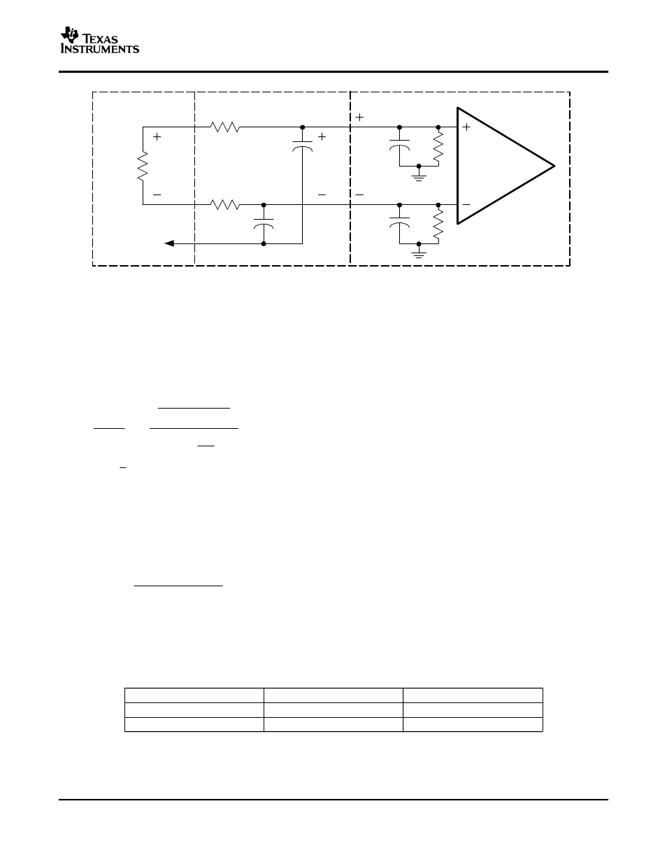
Figure 23. Measurement Low-Pass Filter Derivation Circuit-Class-D APAs
The transfer function for this circuit is shown in Equation 8 where
ω
O
= R
EQ
C
EQ
, R
EQ
= R
FILT
|| R
ANA
and
C
EQ
= (C
FILT
+ C
ANA
). The filter frequency should be set above f
MAX
, the highest frequency of the measurement
bandwidth, to avoid attenuating the audio signal. Equation 9 provides this cutoff frequency, f
C
. The value of R
FILT
must be chosen large enough to minimize current that is shunted from the load, yet small enough to minimize the
attenuation of the analyzer-input voltage through the voltage divider formed by R
FILT
and R
ANA
. A rule of thumb is
that R
FILT
should be small (~100
Ω
) for most measurements. This reduces the measurement error to less than
1% for R
ANA
≥
10 k
Ω
.
An exception occurs with the efficiency measurements, where R
FILT
must be increased by a factor of ten to
reduce the current shunted through the filter. C
FILT
must be decreased by a factor of ten to maintain the same
cutoff frequency. See Table 3 for the recommended filter component values.
Once f
C
is determined and R
FILT
is selected, the filter capacitance is calculated using Equation 9. When the
calculated value is not available, it is better to choose a smaller capacitance value to keep f
C
above the minimum
desired value calculated in Equation 10.
Table 3 shows recommended values of R
FILT
and C
FILT
based on common component values. The value of f
C
was originally calculated to be 28 kHz for an f
MAX
of 20 kHz. C
FILT
, however, was calculated to be 57,000 pF, but
the nearest values of 56,000 pF and 51,000 pF were not available. A 47,000-pF capacitor was used instead, and
f
C
is 34 kHz, which is above the desired value of 28 kHz.
Table 3. Typical RC Measurement Filter Values
MEASUREMENT
R
FILT
C
FILT
Efficiency
1000
Ω
5,600 pF
All other measurements
100
Ω
56,000 pF
23