Diagrams/esquemas – Tripp Lite Alternative Power Source User Manual
Page 36
36
36
OUTPUT/NEUTRA
OUTPUT/HOT
GROUND
INPUT/NEUTRA
INPUT/HOT
“FOR USE WITH COPPER WIRE ONLY”
Diagrams/Esquemas
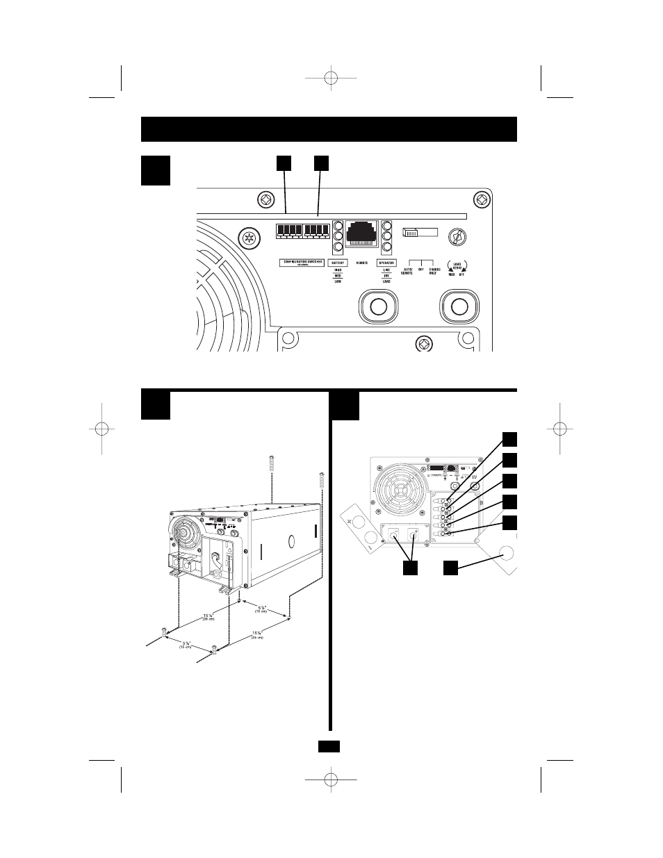
See “Configuration”, pg. 5. 1.1 is DIP Switch Group A. 1.2 is DIP Switch Group B.
Refiérase a la sección “Configuración”, página 22. 1.1 representa el Grupo A de Interruptores DIP. 1.2 representa el Grupo B de
Interruptores DIP
See Hardwire Electrical Connections, pg. 10.
3.1 is the cover plate;
3.2 are the DC input terminals;
3.3 is the output neutral (white);
3.4 is the output hot (black);
3.5 is the input/output ground tie point;
3.6 is the input neutral (blue); and
3.7 is the input hot (brown).
Refiérase a la sección “Conexiones Eléctricas Directas
al Circuito”, página 28.
3.1 representa la cubierta;
3.2 representan las terminales de entrada de CD;
3.3 representa la terminal neutra de salida (blanca);
3.4 representa la terminal positiva de salida (negra);
3.5 representa la terminal entrada/salida de tierra;
3.6 representa la terminal neutra de entrada (azul) y
3.7 representa la terminal positiva de entrada (café).
1
1.2
2
3
1.1
3.3
3.4
3.5
3.6
3.7
3.2
3.1
200110086 120V APS MV-cabinetEn-Sp 93-2006.qxd 1/4/02 10:38 AM Page 36