Accessories, Controls and indicators, Configuration – Tektronix 070-9180-01 User Manual
Page 14
Getting Started
1–4
Option 01 VXI Interface Module User Manual
Accessories
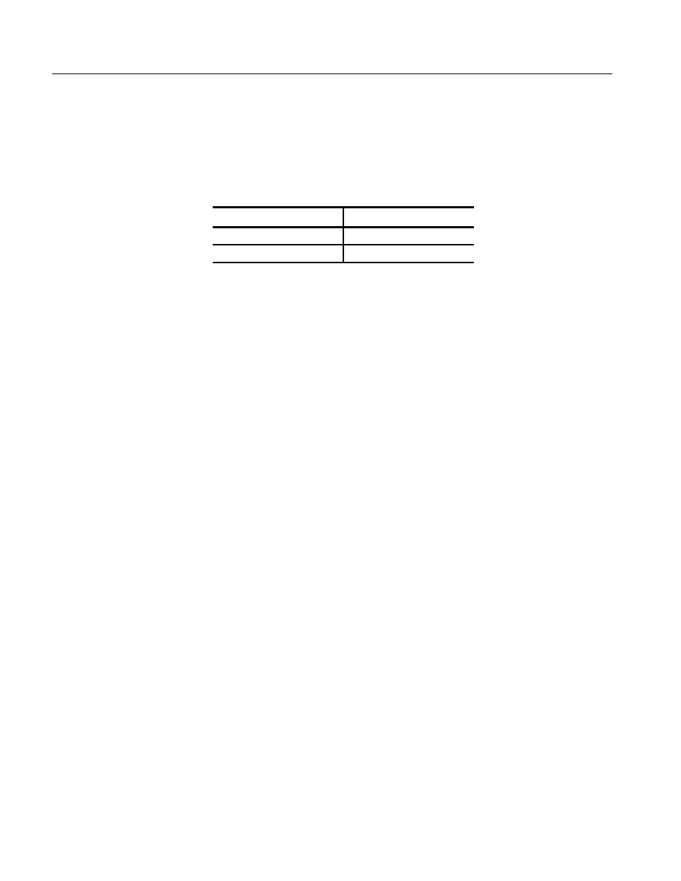
Table 1–1 lists the standard accessories included with the Option 01.
Table 1–1: Standard Accessories
Accessory
Part Number
Option 01 User Manual
070-9180-XX
Option 01 Reference
070-9198-XX
Controls and Indicators
The following controls are provided to select the functions of the Option 01
operating environment.
The Logical Address switches and
VMEbus Interrupt Level Select switch
must be
correctly set to insure proper operation. See Configuration for details on how to
set the switches.
Configuration
The following switches must be correctly set to ensure proper operation. Refer to
Figure 1–1 for their physical locations.
Each functional module in a VXIbus System must be assigned a unique logical
address, from 1 to decimal 255 (hexadecimal FF). The base VMEbus address of
the Option 01 is set to a value between hexadecimal C0 (C000
16
) and hexadeci-
mal FF (FFC0
16
) by two hexadecimal rotary switches. Align the desired switch
position with the arrow on the module shield.
The physical address of the instrument is on a 64 byte boundary. If the Logical
Address switch representing the most significant digit (LA–HI) of the logical
address is set to position X and the switch representing the least significant digit
(LA–LO) of the logical address is set to position Y, then the base physical
address of the Option 01 will be [(40
16
×
XY
16
) + C000
16
].
Switches
Logical Address Switches
Artisan Technology Group - Quality Instrumentation ... Guaranteed | (888) 88-SOURCE | www.artisantg.com