Quick installation, Plug your equipment into your ups, Turn your ups on – Tripp Lite 450-1500VA User Manual
Page 3: Optional db9 connection
3
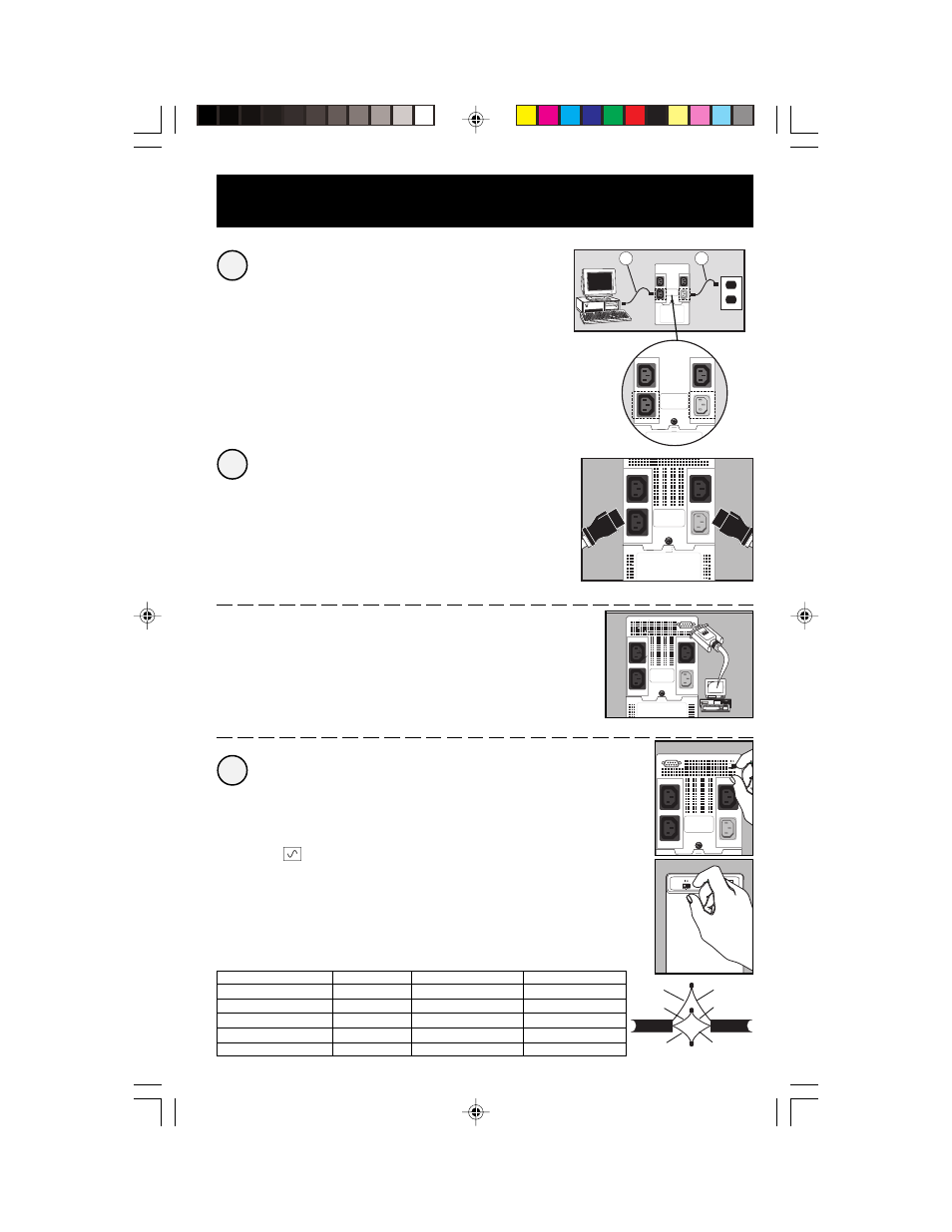
Quick Installation
Connect your computer to the
UPS, and the UPS to an electrical
outlet.
1. Unplug your computer’s power cord from both your AC
outlet and your computer’s AC input.
2. Insert the female plug of the power cord that came with
your UPS (A) into your computer’s AC input. Insert the UPS
cord’s male plug into any of your UPS’s female output
receptacles.
3. Insert the female plug of your computer’s cord (B) into
your UPS’s AC input. Insert the male plug of your
computer’s cord into your AC outlet.
Plug your equipment into
your UPS.
Your UPS is designed to support only computer equipment.
You will overload your UPS if you connect household
appliances, laser printers or surge suppressors.
Cords and receptacle adapters are available from Tripp
Lite to accommodate most outlet configurations. If
rewiring is necessary, refer to the Wire Color-Code Chart
at the bottom of the page.
–Optional DB9 Connection*–
Using Tripp Lite cable, connect the serial port of your
computer to the serial port of your UPS. Load software and
run installation program appropriate to your operating
system.
*Your UPS will function properly without this connection.
Turn your UPS ON.
Set the System Enable Switch (UPS back panel)
to “ON” (or “ENABLE/I”).
(See Figure 1)
This switch activates the battery charger and
microprocessor.
The “
XXX
” light will flash until you engage the ON/
Standby Switch to activate the “ON” mode.
Engage the momentary ON/Standby Switch (UPS
front panel) and release it to activate the “ON”
mode and supply power to the UPS receptacles.
(See Figure 2)
3
2
1
A
B
SEE MANUAL
Figure 2
ON/Standby Switch
Figure 1
System Enable Switch
Wire Color
Wire 1
Wire 2
Wire 3
American
Black
White
Green
European
Brown
Blue
Green/Yellow
Wire Reference
Wire 1
Wire 2
Wire 3
American
Line 1
Neutral
Ground
European
Line 1
Line 2 or Neutral
Ground
EURO
Black
White
Green
Brown
Blue
Green/
Yellow
AMER
200311039 93-xxxx SmartINT1500 Owner's Manual_English.p65
11/25/2003, 11:56 AM
3