2 mechanical component layout – Toshiba E-STUDIO900 User Manual
Page 180
PTM 7-5
B070/B071
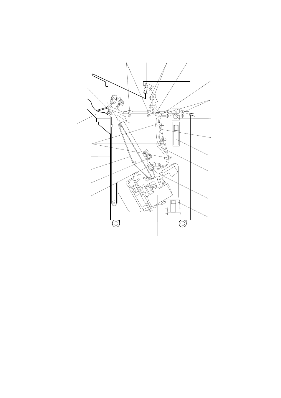
7.2 MECHANICAL COMPONENT LAYOUT
1. Upper
Tray
2. Middle Transport Rollers
3. Upper Tray Exit Roller
4. Upper Transport Rollers
5. Tray Junction Gate
6. Stapler Junction Gate
7. Entrance
Rollers
8. Punch
Unit
9. Pre-stack Junction Gate
10. Punch Waste Hopper
11. Pre-stack Tray
12. Stack Plate
13. Staple Waste Hopper
14. Stapler
15. Alignment Brush Roller
16. Positioning Roller
17. Stack Feed-out Belt
18. Shift Tray Drive Belt
19. Lower Transport Rollers
20. Shift Tray
21. Shift Tray Exit Roller
B478V500.WMF
10
9
15
14
3
11
12
13
16
17
18
20
19
21
4
7
8
1
2
5
6