Rs-232, Pneumatic system, Lectrical and – Teledyne 300M User Manual
Page 20: Neumatic, Onnections, 4 rs-232, 5 pneumatic system
Teledyne API Model 300M CO Analyzer Instruction Manual, 04033, Rev. A
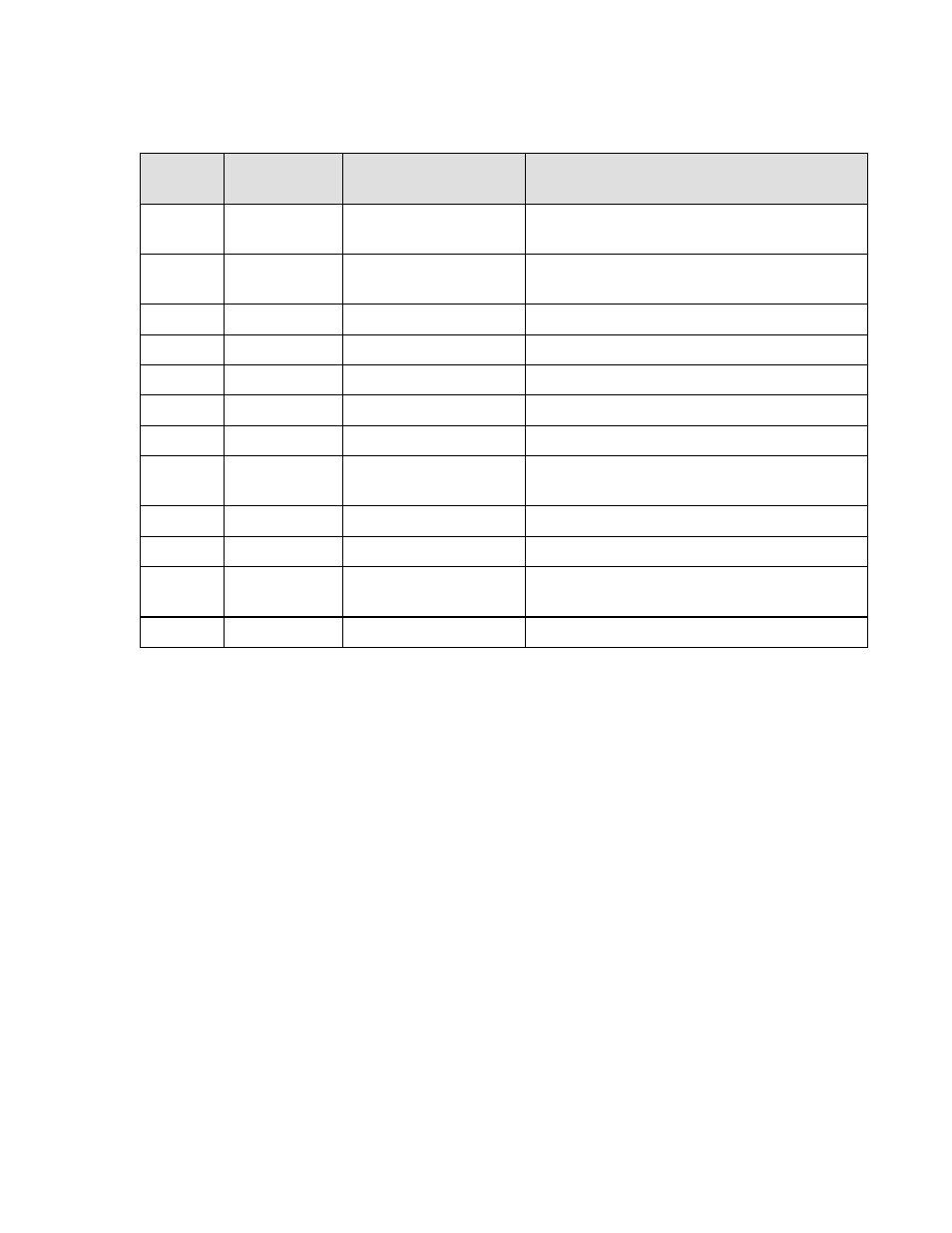
Table 1-1: Status Outputs
Output#
Pin Pair
(Low, High)
Definition
Condition
1 1,2
ALARM
1
Gas concentration is exceeding the Hi set
limit.
2
3,4
ALARM 2
Gas concentration is exceeding the HiHi set
limit.
3
5,6
SYSTEM OK
True if no alarm conditions exist
4
7,8
TEMP ALARM
True if any temp warning exists
5
9, 10
DIAG MODE
True if in diagnostic mode
6
11,12
POWER ON
True if main power is on
7
13,14
PRESS ALARM
True on low pressure
8 15,16
HIGH
RANGE
SELECTED
True if the auto-range function has switched
the analyzer into high range.
9
17,18
FLOW ALARM
True if a flow warning exists
10 19,20
RESERVED
11 21,22
SOURCE
WARNING
True if the analyzer source intensity is out
of limits.
12 23,24
RESERVED
1.6.4 RS-232
The RS-232 connection is a male, 9-pin D-sub connector at the location shown in Figure 1-3.
See also Appendix A for additional information.
1.6.5 Pneumatic System
The Model 300M is equipped with a vacuum pump capable of pulling 800 cc/min across a flow
restrictor. This allows a smooth, stable flow of sample through the analyzer.
Sample enters the analyzer through a particulate filter element (47 mm diameter) mounted
immediately behind the front panel. The sample then enters directly into the sample cell. Please
see Figure 1-1 for a flow diagram and Figure 1-4 for pneumatic connections.
1-12