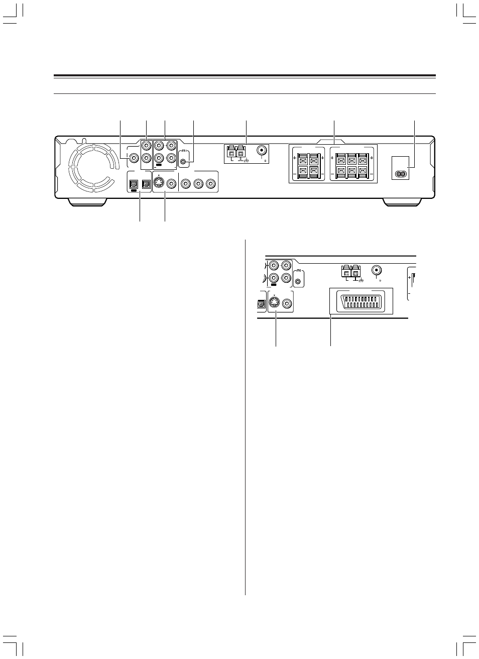
Index to parts and controls, Rear panel, 3 md/cdr/tape in/out jacks [22 – Onkyo DR-L50 User Manual
Page 16: 4 z remote control connector [23, 7 ac inlet [26, 9 video output (video/s video/component) jacks [18, Av connector terminal [19, European models
16
Shapes of jacks vary depending on the area in which it was
purchased.
1 SUB WOOFER PRE OUT jack [20, 21]
This terminal is for connecting an active subwoofer.
2 TV/LINE IN jacks [18,19, 22]
This terminal is for connecting audio output terminals of TV, VCR or
other video equipment.
3 MD/CDR/TAPE IN/OUT jacks [22]
These terminals are for connecting to the recording input and
output terminals of an MD recorder, CD recorder or tape deck.
4 z REMOTE CONTROL connector [23]
Connect the Onkyo components that have
z
connectors such as
a MD recorder, and cassette tape deck using the
z
cables
provided with them. When these components are interconnected,
they can be controlled from the remote controller provided with the
DVD Receiver.
After connecting the
z
connectors, check the operation of the
remote controller buttons for use in controlling other components.
5 ANTENNA terminals [24, 25]
These terminals are for connecting the FM antenna and AM
antenna.
6 FRONT SPEAKERS, CENTER SPEAKER and SURROUND
SPEAKERS terminals [21]
Speaker terminals are provided for the front left, front right, center,
surround left and surround right speakers. Speaker outputs are
compatible with banana plug connectors.
7 AC INLET [26]
Connect supplied AC power cord to this terminal.
8 DIGITAL OPTICAL IN/OUT jacks [18, 19, 22]
These are the digital audio input and output jacks. The digital input
works in combination with the analog TV/LINE IN jacks. Connect
the digital output from your TV or satellite tuner (MD player, etc.) to
DIGITAL OPTICAL IN. Set the INPUT SELECTOR to TV/LINE IN to
play the digital sound. Connect the DIGITAL OPTICAL OUT to a
digital recording device (MD recorder, CD recorder, etc.). Do not
connect the DIGITAL OPTICAL OUT if the digital output from the
same component is connected to the DIGITAL OPTICAL IN.
9 VIDEO OUTPUT (VIDEO/S VIDEO/COMPONENT) jacks
[18]
The monitor output includes RCA type, S video and component
configurations. This output is for connecting television monitor or
projector.
(European models)
0 VIDEO OUTPUT (VIDEO/S VIDEO) jacks [19]
The monitor output includes RCA type and S video. This output is
for connecting television monitor or projector.
- AV CONNECTOR terminal [19]
Use a 21-pin SCART cable to connect to a TV or monitor
compatible with this type of connection. Both audio (2 channel
stereo) and video (Video, S-video, and RGB) signals are output
from the AV CONNECTOR.
Index to Parts and Controls
■Rear panel
AC INLET
PREOUT
SUB
WOOFER TV/LINE
MD/CDR/TAPE
DIGITAL
OPTICAL
VIDEO OUTPUT
AUDIO
REMOTE
CONTROL
AM
FM 75
SURROUND
SPEAKERS
FRONT SPEAKERS
CENTER
R
L
S VIDEO
VIDEO
COMPONENT
ANTENNA
IN
Y
P
B
P
R
IN
IN
OUT
L
R
R
L
OUT
ANTENNA
1
2
4
5
6
7
3
8
9
TV/LINE
MD/CDR/TAPE
TAL
AL
VIDEO OUTPUT
REMOTE
CONTROL
AM
FM 75
S VIDEO
VIDEO
ANTENNA
IN
IN
IN
OUT
L
R
ANTENNA
AV CONNECTOR
0
-
Other than European models
European models