2 rear panel, The rear panel connections are shown in figure 2.2 – Omega WI8XX-U User Manual
Page 12
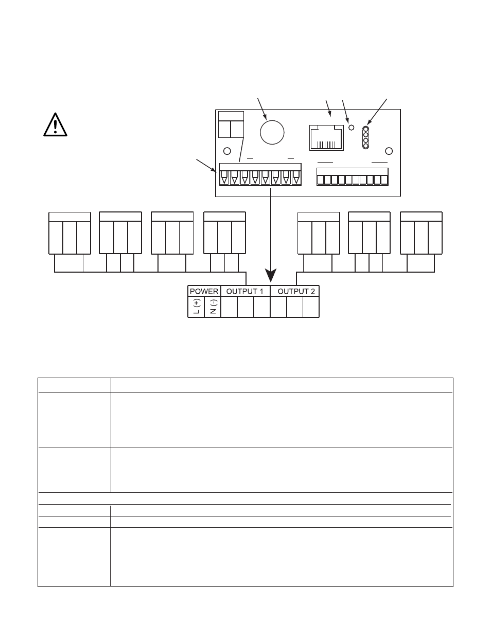
2.1.2 Rear Panel
The rear panel connections are shown in Figure 2.2.
Figure 2.2 Rear Panel Power and Output Connections
Table 2.2 Rear Panel Connector
POWER
AC/DC Power Connector: All models
OUTPUT 1 Based on one of the following models:
Relay SPDT
Solid State Relay (SSR)
Pulse
Analog Output (Voltage and Current)
OUTPUT 2 Based on one of the following models:
Relay SPDT
Solid State Relay (SSR)
Pulse
Network Communication Interface Section:
ETHERNET RJ45 interface for 10BASE-T connection.
RESET
Button: Used for power reseting the Ethernet board.
ACTIVITY
LED (Red) Blinking: Indicates network activities (receiving or
sending packets).
NET LINK
LED (Green) Solid: Indicates good network link.
TX
LED (Yellow) Blinking: Indicates transmitting data to the serial port.
RX
LED (Green) Blinking: Indicates receiving data on the serial port.
ACTIVITY
NET LINK
TX
RX
8
1
ETHERNET
RST
RJ45 10BASE-T
CONNECTION
RESET
BUTTON
LED
INDICATORS
ANTENNA
LOCATION
POWER
L(+)
N(-)
1
6 OUTPUTS
7
8
7
8
NOT USED
SSR
RELAY
PULSE
SSR
RELAY
PULSE
ANALOG
8 7 6 5 4 3 2 1
OUTPUT 1
OUTPUT 1
OUTPUT 1
OUTPUT 1
OUTPUT 2
OUTPUT 2
OUTPUT 2
POWER / OUTPUT
CONNECTOR
6 5 4
3 2 1
3 2 1
3 2 1
6 5 4
6 5 4
6 5 4
NO
NC
C
CUR
V
RTN
PUL
RTN
NO
C
NO
NC
C
PUL
RTN
NO
C
6
Use copper conductors
only for power connections