Rane SRM 66 User Manual
Page 6
Manual-6
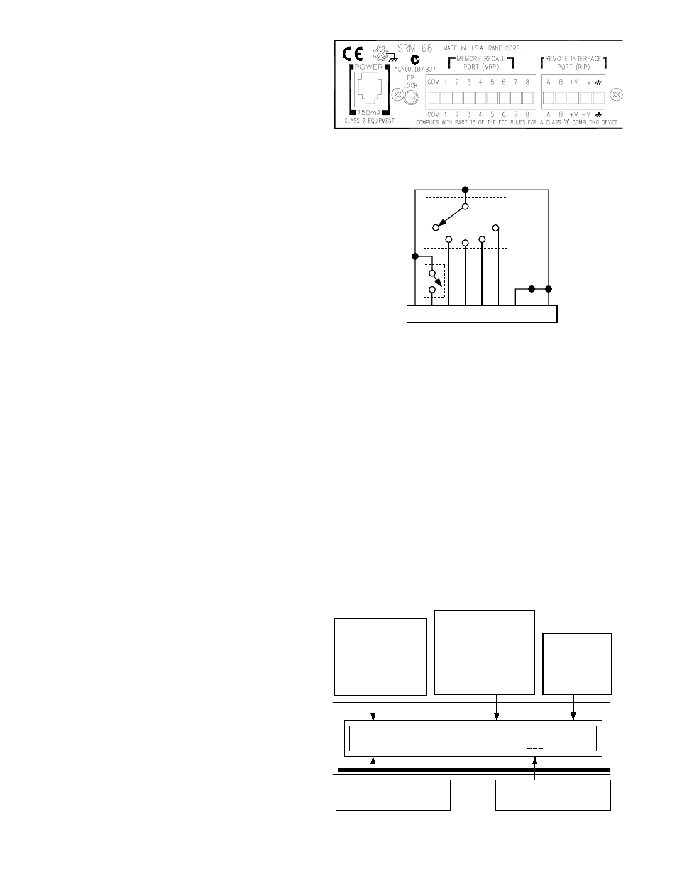
Figure 7. Memory Recall Port (MRP)
and Remote Interface Port (RIP)
Figure 8. MRP Wiring
8
7
6
5
4
3
2
1
C
Mic
Switch
Memory
Switch
Paging
Mode
SR 1L Troubleshooting
Double-check all wiring for accuracy before power is
applied via the SRM 66. A single LED on the SR 1L should
light immediately after SRM 66 power is applied. A blinking
LED indicates that it has not yet detected communication on
the Port. This is common until the SRM 66 has fully initial-
ized but should not happen after that point. If after hook up
and SRM 66 power up, an SR 1L LED blinks or does not
respond, one of several problems is to blame. Either the
wiring is incorrect, the SR 1L address is invalid (must be
between 1 and 7), the SRM 66 is not in SR1 mode (under the
RIP parameter in the Memory LCD page), or the SR 1L’s
ENCODER LOCK terminal is shorted, thus locking out the
encoder. Also, the SRM 66 Remote to Group assignment may
be set to Off, thus disabling the entire SR 1L, not just the
encoder.
Alternate Remote Interface Port Modes
There are three Remote Interface Port modes. The default
RIP mode allows communication to SR 1L Remotes. To
permit SR 1L Remote functionality, the RIP parameter setting
on the Memory page must be set to SR1 (the default).
When using the DSC 1 accessory product, the RIP
parameter must be set to DSC. (See DSC 1 & SRM Exchange
Software on page Manual-7.) When using the SRM 66’s
Master Slave feature, RIP must be set to SLAVE, see the next
section.
Advanced SRM 66 & SR 1L Applications
A single SR 1L can control Output Groups across multiple
SRM 66s. For more information on this Master/Slave func-
tionality, see RaneNote 142, “Advanced Applications of the
Ingenious SRM 66 and SR 1L.”
For room controller fans out there, two more RaneNotes
of interest are RaneNote 138, “Using a Control System with
an SRM 66” and RaneNote 139, “Using SR 1Ls with Other
Rane Products.” These RaneNotes happen to cover AMX, but
the Device Control Language and complete communications
details are covered for easy incorporation into Crestron
systems. See the ADVANCED APPLICATIONS & ACCES-
SORIES section below for more advanced functionality.
All of these RaneNotes are available in PDF form at
http://www.rane.com/library.htm or we’ll email it to you if
you ask [email protected], or we’ll fax or snail mail it if you
ask real nice.
Memories
Twenty-four non-volatile Memories can save up to
twenty-four system configurations. Each Memory contains
the following parameters.
Mix Source Routing
Input 1-2-3-4-5-6 to each Output
Mix Source Levels
+6 dB to -25 dB for each Output
Master Level Reduction +0 dB to -59 dB for each Output
Limit Threshold
Max (0 dBr) to -28 dBr, each Output
Output to Group Assignments
Remote to Group Assignments
Memories are stored and recalled using the Memory page
shown in Figure 9.
Mem[n]*
Store
Recall
Memory [n] [Stored]!
[ n]
[ n]
*
RIP
[SR1]
Memory page. The
indicates current
parameter settings do
not match the recalled
Memory; [n] indicates
the last recalled
Memory.
Memory location
to Recall. Select
Memory with
DATA wheel and
press EXE to
Recall.
Selects mode for the
Remote Interface Port.
Select SR1 when used
with SR 1L Remote
devices. DSC mode allows
external communication
options. Slave allows
master/slave operation.
Memory location to Store.
Select Memory with DATA
wheel and press EXE to Store.
After Execution, this confirms
that Memory [n] has been
Stored
or Recalled.
Figure 9. Memory Page
Memory Recall Port
In addition to the Memory page, the SRM 66 provides a
Memory Recall Port (MRP). This port allows remote switch
closures to recall any of the twenty-four system Memories.
The first eight Memories recall with simple switch closures
on the eight MRP pins (see the Normal section of Table 1). A
binary wiring mode allows accessing all 24 Memories (see the
Binary section of Table 1).
“Paging” mode provides installers an easy way to config-
ure a system which uses a single switch (such as a push-to-
talk mic switch) to toggle between two sequential Memories
to change source levels. See Figure 8 and Table 1.
FP LOCK
The recessed FP LOCK switch (on the rear) locks out all
front panel control except for Group Levels and Memory
Recall. With FP LOCK engaged, the SR 1L Remotes are able
to control Group Levels, and all Edit Pages are viewable but
not editable.