Rinnai 37AHB SERIES User Manual
Page 51
Rinnai Corporation Hydronic Furnace (37AHB) Manual
51
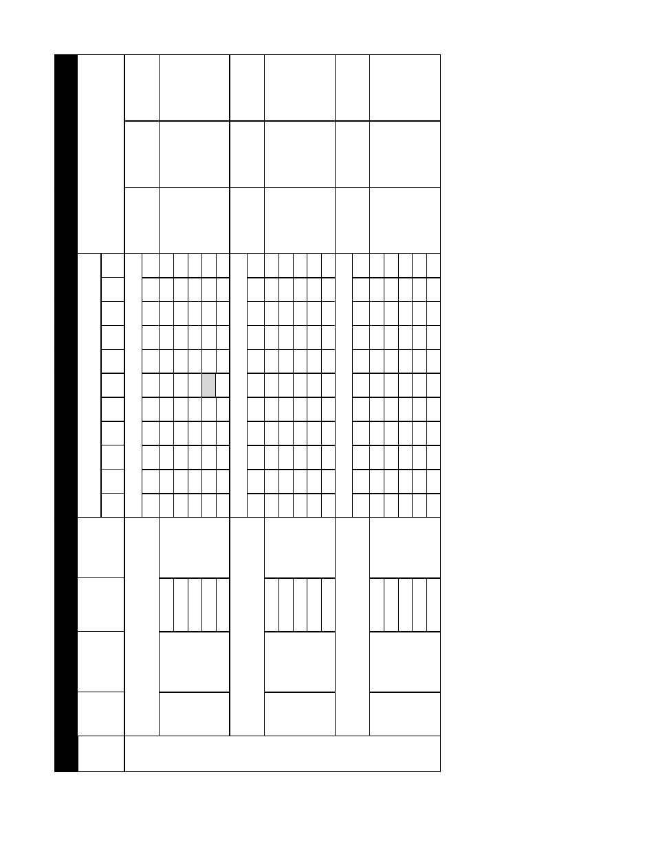
N
O
T
E
S
:
1.
E
W
T
- En
teri
ng
W
ater Tempe
ratur
e (F)
.
2.
CFM - Air
flow
in (C
ubic Feet per
Minute).
3.
Legs - 3
in
ch
diame
ter
flex
ible du
cts to
diffu
ser
s.
4.
1 MBH =
1000
BTU/H.
5.
Shaded b
ox
represents ra
ting
poin
t; re
fer
to
w
iring diagra
m
for
factory
se
t sp
eed
taps.
6.
Number of 3”
diam
eter
leg
s
spe
cifi
ed i
n ta
ble a
bov
e is
fo
r
rating
poin
t o
nly
(i.e
. a
t Ex
ternal S
ta
tic
Pres
sure
of
0
.5
in. w
c. and
speed
TAP3, TAP1, TAP2
, TAP2
for
AHB45
, AH
B60, AHB75, A
H
B90 re
spe
ctiv
ely
). Final
leg
count i
s
to b
e de
termined
b
y the in
stalli
ng
con
tractor
and i
s to
be
based
on
the
follow
ing formula:
NUMBER OF LEG
S
= TOTAL
AVA
IL
ABLE CFM
(A
T THE S
P
ECI
F
IC
E
SP)
/ DESI
RED CFM per LEG
(40, 50, or 60 CF
M)
Ex
ample: Giv
en the
design
point
for
A
H
B045 o
f 0
.8
ESP
, Low
fan
speed
(Ta
p5). From
tabl
e 5
.0
, av
ailable CFM i
s
569 and
the d
esir
ed CFM per
leg
is 50
CFM.
Therefore,
Number of Leg
s =
569/50
= 11
.38
rou
nded dow
n to
11
.
0
0
.1
0.
2
0
.3
0.
4
0
.5
0.
6
0
.7
0.
8
0
.9
1.
0
948
921
891
868
8
4
1
8
1
9
795
772
701
596
567
120
34.
4
33.
5
32
.4
31
.5
30.
6
29.
8
28.
9
28.
0
25.
5
21
.7
20
.6
130
40.
1
38.
9
37
.7
36
.7
35.
5
34.
6
33.
6
32.
6
29.
6
25
.2
24
.0
140
46.
6
45.
2
43
.8
42
.6
41.
3
40.
2
39.
1
37.
9
34.
4
29
.3
27
.9
150
54.
5
53
51
.3
49
.9
48.
4
47.
1
45.
7
44.
4
40.
3
34
.3
32
.6
160
59.
6
57.
9
56
54
.6
52.
9
51.
5
50.
0
48.
5
44.
1
37
.5
35
.6
921
891
864
836
8
1
2
7
8
8
768
742
699
594
559
120
33.
7
32.
6
31
.6
30
.6
29.
7
28.
8
28.
1
27.
1
25.
6
21
.7
20
.4
130
40.
2
38.
9
37
.8
36
.5
35.
5
34.
4
33.
6
32.
4
30.
5
26
.0
24
.4
140
46.
6
45.
1
43
.7
42
.3
41.
1
39.
9
38.
8
37.
5
35.
4
30
.0
28
.3
150
54.
2
52.
4
50
.8
49
.2
47.
8
46.
4
45.
2
43.
7
41.
1
34
.9
32
.9
160
60.
2
58.
2
56
.4
54
.6
53.
0
51.
5
50.
2
48.
5
45.
7
38
.8
36
.5
803
768
740
712
6
8
2
6
5
2
628
596
569
541
510
120
32.
2
30.
8
29
.7
28
.5
27.
3
26.
1
25.
2
23.
9
22.
8
21
.7
20
.4
130
38.
2
36.
5
35
.2
33
.8
32.
4
31.
0
29.
8
28.
3
27.
0
25
.7
24
.2
140
44.
9
42.
9
41
.4
39
.8
38.
1
36.
5
35.
1
33.
3
31.
8
30
.2
28
.5
150
51.
4
49.
2
47
.4
45
.6
43.
7
41.
7
40.
2
38.
2
36.
4
34
.6
32
.6
160
57.
4
54.
9
52
.9
50
.9
48.
8
46.
6
44.
9
42.
6
40.
7
38
.7
36
.5
EW
T
(
O
F)
NO
M
INA
L
HEA
T
IN
G
CA
P
A
CI
TY
Ex
te
rn
a
l
St
a
ti
c
Pr
es
sur
e
(
E
S
P
) i
n
. W
.C
.
SUP
P
ORT
S
C
OOL
IN
G C
A
P
.
RA
NG
E (
T
O
N
S)
TB
D
See
N
ot
e 6.
TB
D
S
ee N
ot
e 6.
M
ax
im
um
Legs @
40 C
F
M
/Leg
37A
HB0450
8KA5 +
RE
U-V
A2
024WD(A)
-UC
A
H
B4
5
+
R6
3
L
S
e
2
A
IRFLOW
(
C
FM
)
TA
P
3
(H
)
2.
0
NE
T
HE
A
TI
N
G
CAP
A
CI
TY
(M
B
H
)
13
A
H
B4
5
+
R6
3
L
S
e
2
A
IRFLOW
(
C
FM
)
TA
P
4
(M
)
2.
0
NE
T
HE
A
TI
N
G
CAP
A
CI
TY
(M
B
H
)
TB
D
S
ee N
ot
e 6.
M
ini
m
um
Legs
@
60 C
F
M
/Leg
A
H
B4
5
+
R6
3
L
S
e
2
A
IRFLOW
(
C
FM
)
TA
P
5
(L
)
1.
5
NE
T
HE
A
TI
N
G
CAP
A
CI
TY
(M
B
H
)
TB
D
S
ee N
ot
e 6.
M
ini
m
um
Legs
@
60 C
F
M
/Leg
O
pt
im
al
Legs
@
50
C
F
M
/L
eg
16
20
N
um
ber
of
3"
di
am
et
er
br
an
ch
le
gs
appl
ic
abl
e t
o
H
ig
h
V
el
oc
ity
S
yst
em
s on
ly
.
U
ded o
nl
y i
f
m
et
hods ot
her
th
an
Tabl
e
3 i
s used t
o
det
er
m
ine du
ct
s
izes
.
M
ini
m
um
Legs
@
60 C
F
M
/Leg
O
pt
im
al
Legs
@
50
C
F
M
/L
eg
M
ax
im
um
Legs @
40 C
F
M
/Leg
T
A
B
L
E 5
.1
9
: A
IR
D
E
L
IVER
Y A
N
D
PE
R
F
O
R
M
A
N
C
E D
A
T
A
(
B
O
T
T
O
M
O
R
S
ID
E
R
E
T
U
R
N
w
/ F
A
C
T
O
R
Y
SU
PPL
IE
D
F
IL
T
ER
)
UNI
T
SI
Z
E
EC
M
S
PEE
D
TA
P
O
pt
im
al
Legs
@
50
C
F
M
/L
eg
M
ax
im
um
Legs @
40 C
F
M
/Leg
TB
D
See
N
ot
e 6.
TB
D
S
ee N
ot
e 6.