Air distribution guide – Rinnai 37AHB SERIES User Manual
Page 29
Rinnai Corporation Hydronic Furnace (37AHB) Manual
29
Air Distribution Guide
Hydronic Furnace, He/ She should adhere to the
following basic rules whenever possible.
1. Duct joints shall be, as a rule, sealed to prevent
leakage of air which may cause objectionable sound.
2. Round ducts are favored to rectangular (on the
supply side) as they offer greater rigidity and higher
efficiency.
3. Fitting selection and placement should also be
carefully studied as the correct fitting and its location
will avoid excessive pressure drops and likely noise
problems.
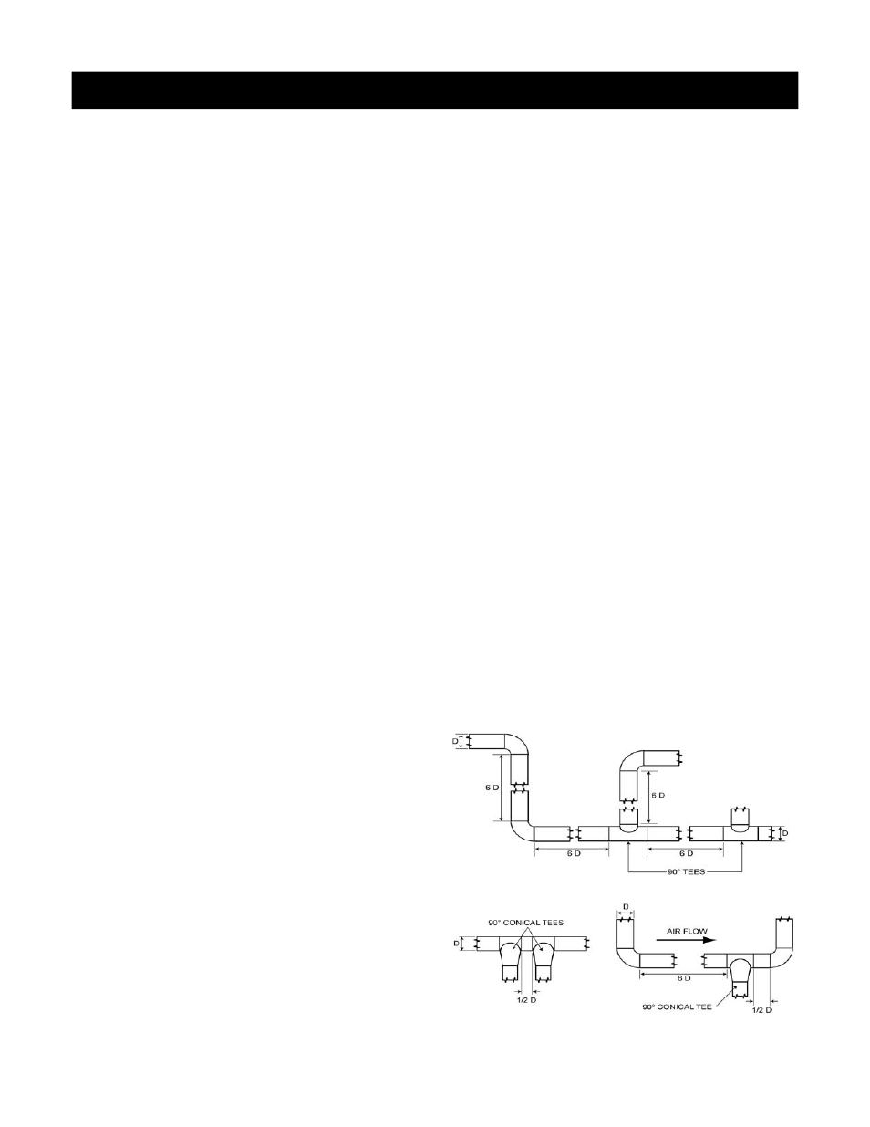
4. Figures 25 and 26 illustrate the critical distance as
regards high velocity ducting system design.
Additionally, when laying out the header section for a
typical high velocity system, the following factor must
be considered:
Unless space conditions dictate otherwise, the
take-off from the header should be made using a
90
o
tee or 90
o
conical tee rather than a 45
o
tee.
By using 90
o
fittings, the pressure drop to the
branch throughout the system is more uniform. In
addition, two fittings are normally required when a
45
o
tee is used and only one when a 90
o
fitting is
used, resulting in lower first cost.
Practically speaking, the design of a high velocity
system is basically the same as a low velocity duct
system. If concerns about noise were not a factor,
duct runs could be sized according to the smallest
permissible duct diameter which would be governed
only by the available external static pressure. In
opposition, since noise reduction is paramount in
residential designs, the designer must take special
care to ensure that all duct sizes are compatible with
velocity limits that are associated with both the
discharge and return sides of the planned system.
To all intents and purposes, duct sizing calculations
are based on fan performance and air side accessory
pressure drop data that are provided by original
equipment manufacturers. The importance of
ensuring that the total pressure drop of the longest
circulation path does not exceed the available static
pressure and that velocities does not exceed the
recommended limits cannot be overstated as these
will ensure a quieter system that will deliver the
required capacity to a given space.
It is absolutely overriding for the designer to verify
available static pressure for both supply and return
ducts. The following tables (tables 3 and 4) provide
information about duct sizing (specific to hi-velocity
system) and the redesigned 37AHB series furnaces
respectively.
To employ table 3 the designer must have generated
at least the following information: total system required
airflow (in CFM), and maximum number of 3 inch
diameter supply legs based on 50 CFM per leg.
Table 4 “Specification Sheet” summarizes the
performance and other technical characteristics of the
37AHB series furnaces and their subsystems.
Some specification numbers are generated by
numerical methods and are therefore statistical means
based on the testing of three or more samples.
Use both tables in conjunction with good engineering
practice together with all codes and ordinances having
jurisdiction.
Figure 25:
Recommended Critical Distance between Elbows and 90
O
Tees for a Typical High Velocity System
.
Figure 26:
Recommended Critical Distance between Elbows and 90
O
Conical Tees for a Typical High Velocity System.