23 figure 16: tcp/ip communication module wiring – Roberts Gorden UltraVac NEMA 4 User Manual
Page 29
SECTION 5: C
OMMUNICATIONS
23
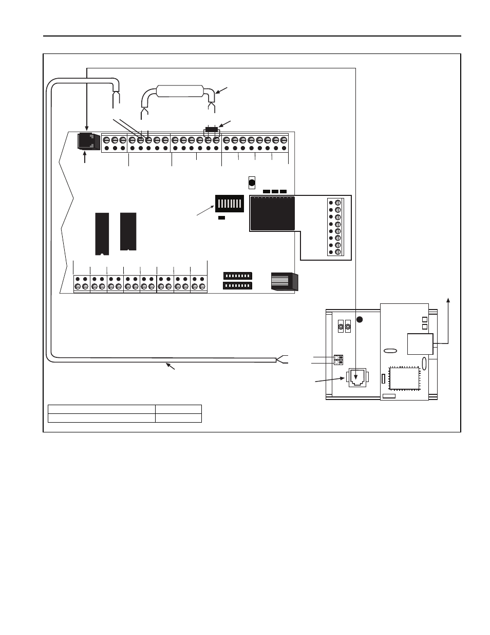
FIGURE 16: TCP/IP Communication Module Wiring
+
-
1
+
-
2
+
-
4
+
-
3
+
-
5
+
-
6
+
-
7
+
-
8
+
-
+
-
REF
RS485 COMM
REF
+
-
1
+
-
2
+
-
3
+
-
4
METER INPUTS
UNIVERSAL INPUTS
IN
OUT
ADDRESS
RESET
10VDC
499 OHM
OFF
ON
OUT
IN
G
IN
OUT
G
G
G
+5
+32
AUX POWER
RS232 DIRECT
RI
CD
OH
CPU
+-
1
+-
2
+-
3
+-
4
RED
BLACK
RED
BLACK
RED
BLACK
120 ohm resistor (included)
w/ P/N 10080440
Shrinkwrap
RS-232
Direct Port
Dip Switch #1
set to ON
Red +
Black -
RS-45
Jack
Ethernet
Cable
to LAN
RJ-11
Jack
Standard 4 Wire Phone Cord (included)
Communications Circuit
Equalizer Wiring (included)
+
-
module power wire
Description
Part Number
TCP/IP Communication Module
10080440
It is important that the module power wire is connected as shown
(black=5 V- / red= 5 V+) wire orientation. Make sure to verify
connection before connecting to the control board.