17 roberts gordon, Pump vfd assembly ( 1 ø input vfd model shown), Zone 3 burners – Roberts Gorden UltraVac NEMA 4 User Manual
Page 23: For 460 v input vfd models, M16/12.p
SECTION 4: T
YPICAL
E
XTERNAL
D
IAGRAMS
17
ROBERTS GORDON
®
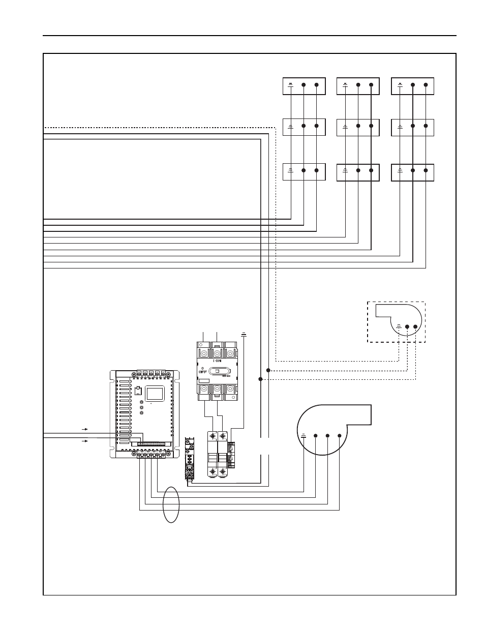
ULTRAVAC™ Central Controller External Wiring (continued)
for 115 V and
230 V input
VFD models.
VFD Power
Supply
(1 Ø input
VFD model shown,
see NOTE 3)
L1
L2
T
1
Pump
VFD Assembly
( 1 Ø input
VFD model shown)
L1
L2
L1
L2
L1
L2
L1
L2
L1
L2
230 V
3 Ø
0-60 Hz
To
Terminal 5
To
Terminal 2
L1
L2
Zone 3
Burners
L1
L2
L1
L2
Outside Air
Blower
(optional)
Zone 2
Burners
Zone 1
Burners
T
2
T
3
Continued
From
Previous Page
To Terminals
13 and 14
Motor Power Supply
(see NOTE 7)
460 V
3 Ø
0-60 Hz
for 460 V
input VFD
models.
or
M16/12.P
M16/12.P
1
2
5
6
11
13A
13B
13E
25
16
17
PE
PE
W
V
U
L2/N
L1
B-
PE
B+