Power input – Roberts Gorden UltraVac NEMA 4 User Manual
Page 16
ROBERTS GORDON
®
ULTRAVAC™ C
ONTROLLER
I
NSTALLATION
M
ANUAL
10
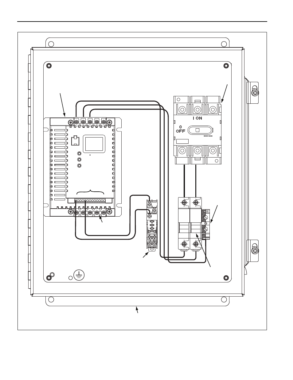
FIGURE 3: Variable Frequency Drive Components (Factory pre-wiring shown)
M16/12.P
M16/12.P
Power Input
1
2
5
6
11
13A
13B
13E
25
16
17
PE
PE
W
V
U
L2/N
L1
B-
PE
B+
Variable
Frequency Drive
(1 Ø input model shown)
Terminal Inputs
230 V 3 Ø or
460 V 3 Ø outputs
Grounding
Block
120 V signal from relay board
output #8
Relay
120 V
Rotary
Disconnect
Input Fuse Holder
(1 Ø input model shown, 3 Ø input models have an
additional input fuse holder and VFD power input.)
VFD Enclosure
(Standard Enclosure Shown)