Renesas MCU Board for PC4504 Emulator System M34570T-MCU User Manual
Page 20
( 18 / 34 )
(2) Connector J4
Use the 2-wire cable for external trigger signals (included) for the connector J4 (for external trigger
signals). Connect the black clip of the external trigger cable to GND, and use the white clip for external
trigger signal input. External signals are used as external trigger breaks, or event input of trace points
by an external trigger. Table 4.5 lists the pin assignments of the connector J4.
Table 4.5 Pin assignments of connector J4
Figure 4.5 Pin layout of connector J6
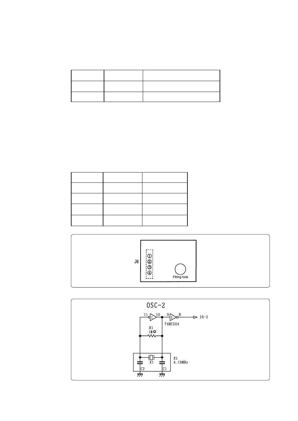
(3) Connector J6
The connector J6 is a connector used to connect an oscillator circuit board OSC-2. Table 4.6 lists
the pin assignments of the connector J6. Figure 4.5 shows the pin layout of the connector J6. For
the 4.19MHz operation with the oscillator circuit board OSC-2, see Figure 4.6.
When changing the frequency of the oscillator, use the oscillator circuit board OSC-2 (only the
connector J1 mounted) included.
When changing the frequency, the constants depend on the oscillator you use. It's advisable to
refer to the values recommended by the manufacturer of the oscillator.
Table 4.6 Pin assignments of connector J6
Figure 4.6 Circuit diagram of OSC-2 (4.19MHz)
Pin No.
1
2
3
4
Signal
V
CC
GND
CLK
GND
Function
Power supply
GND
Clock input
GND
Pin No.
1
2
Signal
TRIG
GND
Function
External trigger signal input
GND input