Roberts Gorden EP 200 Series User Manual
Page 13
SECTION 5: P
UMP
I
NSTALLATION
7
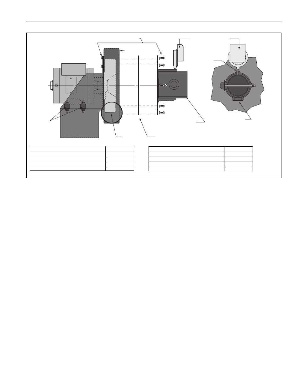
FIGURE 3: Pump Assembly
5.1.3 Attaching the Inlet Plate Assembly
Following installation of the pump scroll to the pump
frame, attach the inlet plate assembly to the pump
scroll as follows:
• Place flat washer on the 5/16" x 7/8" screw.
• Position a single section of the gasket against the
face of the pump scroll; align the clearance holes
of the gasket with the mounting holes of the pump
scroll. Loosely install one 5/16" x 7/8" screw
through the gasket segment and into the top cen-
ter mounting hole of the pump scroll to support
the gasket.
• Interlock the remaining gasket segment to the
previously installed gasket segment to complete
the circular gasket.
• Orient the inlet plate assembly as shown. The
1/8" NPT plug should face directly up, and the 1"
NPT plug should face directly downward. Care-
fully position the top center mounting notch of the
inlet plate assembly to engage the mounting
screw positioned
previously.
• Install the seven remaining 5/16" x 7/8" screws
through the notches in the inlet plate assembly
and into the corresponding mounting holes in the
pump scroll.
• Tighten screws to complete installation of the inlet
plate assembly.
• Install pressure switch in 1/8" NPT hole in top of
outlet.
Inlet Plate Assembly
Impeller
Pump Scroll
Gasket (2 pieces)
Partial End View
1" NPT
Rubber
Mounts
5/16 x 7/8" Screws (w/flat washers) - 16 Req'd.
Pressure Switch
1/8 NPT
Description
Part Number
Pressure Switch
90430600
Pump Scroll
01394400
Rubber Mounts
91906100
Impeller
01394602
Description
Part Number
Inlet Plate Assembly Kit
01327400
Gaskets (2)
91406940
Inlet Plate
01327400
Accessory Bag (8 bolts, 8 flat washers)
01311702