Ricoh Monochrome PoCl Camera Link Camera FV-L030B1 User Manual
Page 4
4/32
FV-L030B1
User’s Guide Rev. 1.01
1.2
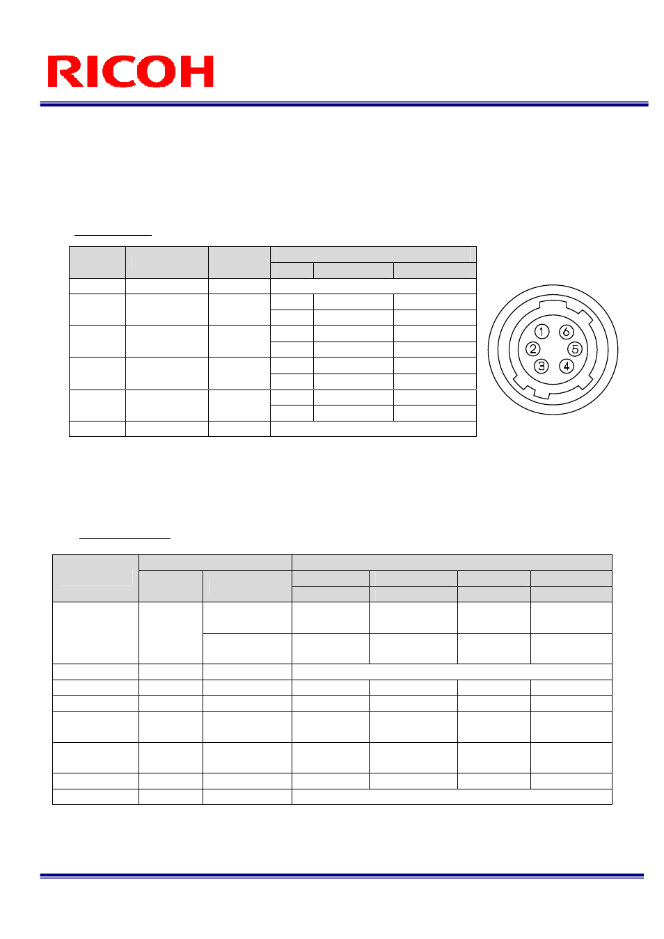
Power-I/O Connector
HR10A-7R-6PB(Hirose)or equivalent
This connector is for the power supply (12Vdc) and input /output signals.
Use HR10A-7P-6S (Hirose) or equivalent for the cable side.
Pin Assignment
Input/output signals can be assigned through the camera setting communication (see table 4).
Trigger input signal can be assigned either on Camera Link connector (CC1) or on the No. 2 pin of the IO
connector through the camera setting communication.
IO Signal Patterns
Voltage
Pin No.
Signal Name
IN / OUT
Low Voltage
High Voltage
1
GND
IN
0V
IN
0 to +0.5
+2.5 to +5.0V
2
I/O-1
IN/OUT
OUT
0V
+3.3V
IN
0 to +0.5
+2.5 to +5.0V
3
I/O-2
IN/OUT
OUT
0V
+3.3V
IN
0 to +0.5
+2.5 to +5.0V
4
I/O-3
IN/OUT
OUT
0V
+3.3V
IN
0 to +0.5
+2.5 to +5.0V
5
I/O-4
IN/OUT
OUT
0V
+3.3V
6
+12Vdc
IN
+12Vdc
Command No.
HR10A-7R-6PB (Hirose)
No.2 Pin
No.3 Pin
No.4 Pin
No.5 Pin
F0H[3..0]
11H[7]
I/O-1 (SP4)
I/O-2 (SP3)
I/O-3 (SP2)
I/O-4 (SP1)
0
(initial setting)
IN/TRG
IN/-
IN/-
OUT/
STROBE
Option 0
(Initial Setting)
0H
1
IN/TRG
OUT/VD
OUT/HD
OUT/
STROBE
Option 1
1H
-
For Test Use Only
Option 2
2H
-
OUT/CC4
OUT/CC3
OUT/CC2
OUT/CC1
Option 3
3H
-
OUT/FVAL
OUT/XSG
OUT/XSUB
OUT/CC1
Option 4
4H
-
OUT/FVAL
OUT/LVAL
OUT/DVAL
OUT/PIC_D9
(MSB)
Option 5
5H
-
OUT/XHD
(high-active)
OUT/EXPDUR
(Exposure)
OUT/TRG
OUT/CC1
Option 6
6H
-
OUT/VD
N/A
N/A
OUT/HD
Others
7H-FH
-
For Test Use Only