Assembly (continued) – RIDGID WL1200LS1 User Manual
Page 18
18
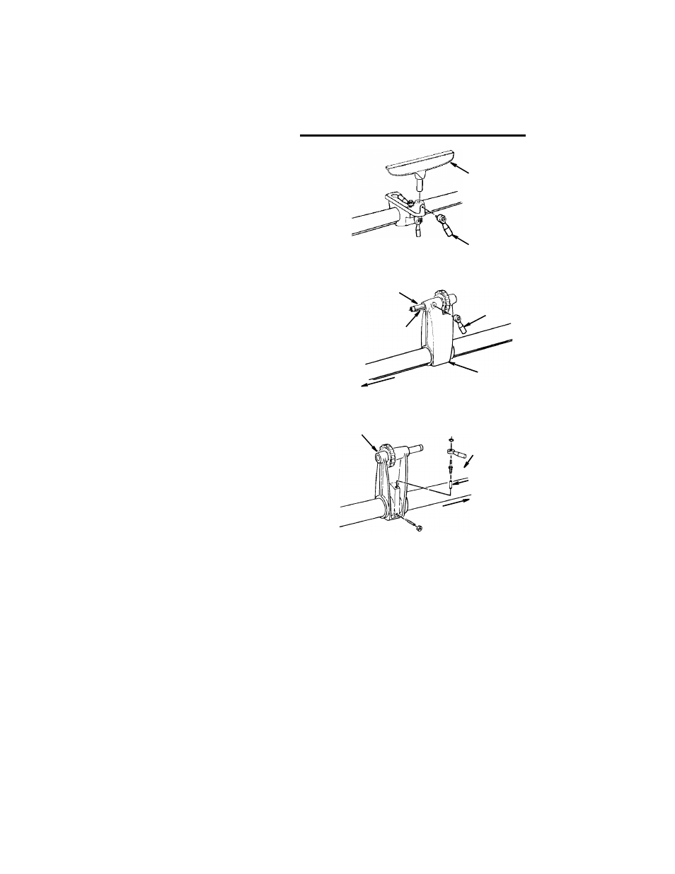
Assembly (continued)
5. Set large tool rest in tool rest holder
and install lever assembly as shown.
6. Slide tailstock assembly onto the tube
and install tailstock ram spindle lock
lever. Be sure that the stud nut
engages the keyed way of the spindle.
7. On the backside of the tailstock,
assemble the locking devices as
shown.
NOTE: Make sure to insert brass shoe
lock before installing lever assembly.
Tool Rest
Lever
Assembly
Lever
Tailstock Ram
Keyed Way
Headstock End
Tailstock
Spindle
Assembly
Assembly
Lever
Headstock End
Tailstock
Brass Shoe
Lock
Assembly
Assembly
See also other documents in the category RIDGID Tools:
- R350CHA (20 pages)
- R350RHA (5 pages)
- R840011 (20 pages)
- 700 (43 pages)
- R844 (16 pages)
- R82015 (20 pages)
- E-924 (1 page)
- R7111 (16 pages)
- K-38 (1 page)
- RB-215 (15 pages)
- R8442 (16 pages)
- JP0610 (44 pages)
- R213BNA (20 pages)
- TP1300 (36 pages)
- TP1300LS (24 pages)
- RT-175 196 (1 page)
- R84040 (20 pages)
- R82320 (16 pages)
- R250AFA (5 pages)
- R8411503 (22 pages)
- R84015 (20 pages)
- AUTOSHIFT R86014 (16 pages)
- R86006 (18 pages)
- R7100 (20 pages)
- R8411511 (22 pages)
- R5010 (18 pages)
- R83001 (20 pages)
- PUMPS (2 pages)
- R6000 (14 pages)
- 904 (1 page)
- JP06101 (40 pages)
- R841151 (22 pages)
- R86007 (32 pages)
- SP6490 (40 pages)
- R8411501 (22 pages)
- R842301 (18 pages)
- R8804 (20 pages)
- DP15501 (32 pages)
- R854 (18 pages)
- FINISH STAPLER R150FSA (20 pages)
- R83015 (20 pages)
- SP-1000 (1 page)
- Drain Cleaner K-40B (51 pages)
- R250SFA (20 pages)
- R7130 (18 pages)