Heater sequence of operation – Raypak 399B-2339B User Manual
Page 33
33
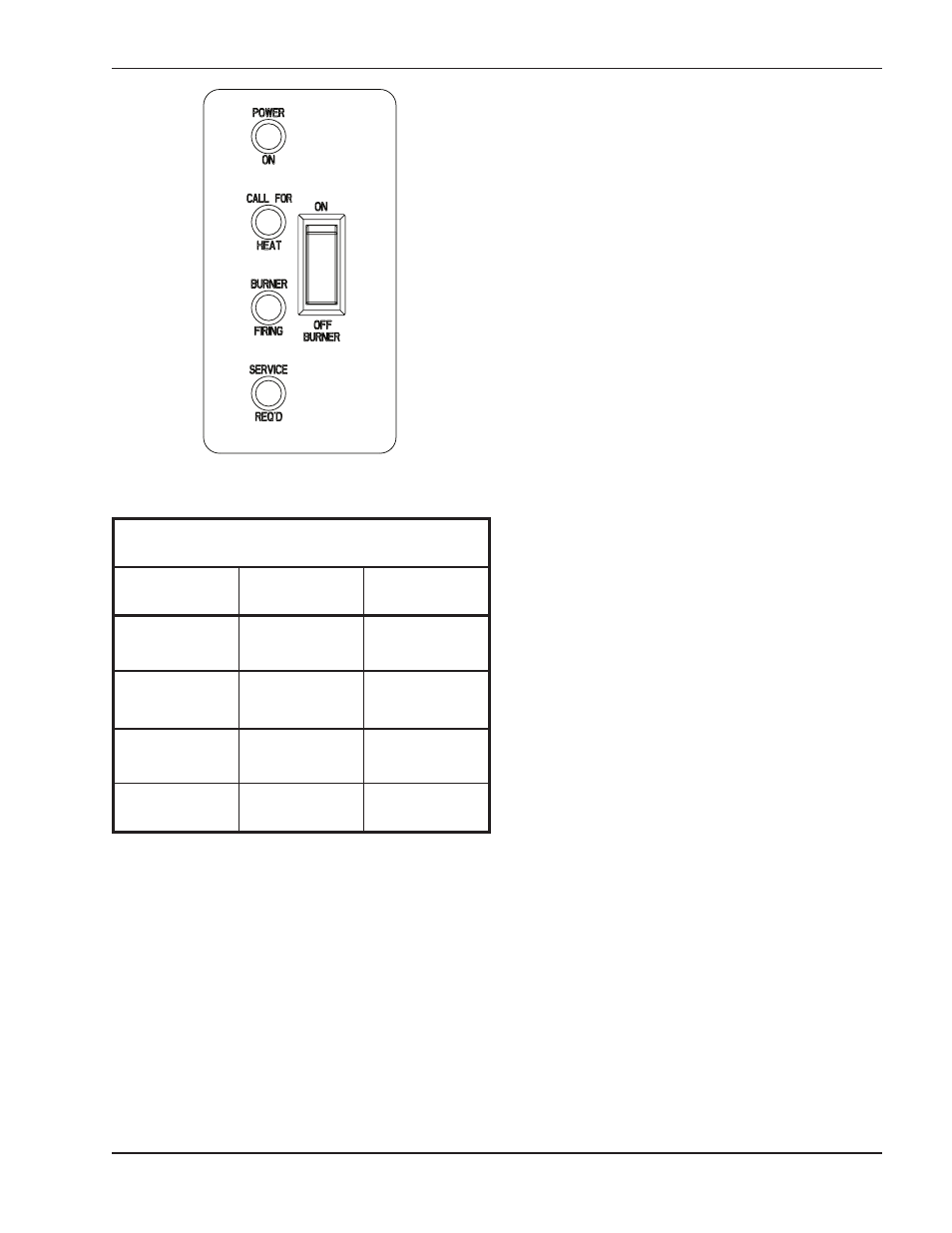
Fig. 27: Status LED Indicator Decal
Heater Sequence of Operation
Models 399B–899B
1.
The black (hot) wire lead goes directly to the main
power switch. This black toggle switch is located
at the middle front of the control compartment.
2.
When the main power switch is placed in the “ON”
position, 120 VAC is applied to the 120 VAC termi-
nal block on the circuit board and the 120/24 VAC
transformer is powered.
3.
120 VAC is waiting at the N.O. contacts of the
pump delay relay.
4.
Terminals L1 and F1 of the ignition module are
powered with 120VAC.
5.
120 VAC power is also applied to the control
power connector on the circuit board.
6.
120 VAC power is waiting at relay contacts K-3 to
energize the heater blower.
7.
The 120/24 VAC transformer outputs 24 VAC.
8.
24 VAC is sent to power terminal L1 of the low
water cut-off board (optional).
9.
24 VAC is applied to the red LED safety shutdown
light on the front of the unit.
10. 24 VAC is applied to the alarm circuit (optional). If
the E-5 sales option (Alarm) is included a 5 sec-
ond time delay relay will not allow the alarm to
sound unless the circuit stays energized for more
than 5 seconds.
11. Power is output from terminal J5-24V of the CPW
board to all of the safeties. All safeties are verified
to ensure that it is safe to operate the heater. The
safety components wired into the diagnostic board
are: Manual reset high limit, low water cut-off
(optional), blocked vent switch, low gas pressure
switch (optional), and high gas pressure switch
(optional).
12. Once all safeties have been verified to be closed a
24 VAC signal is sent to pin P3-16 of J-5 on the
CPW board.
13. 24 VAC power now leaves pin P3-16 of J-5 on the
CPW board and is sent to the auto-reset high limit
(optional). If closed the power now goes to termi-
nal P1-4 of J-5 on the CPW board.
14. Power is applied to terminal 24V of the pump
delay relay to energize the timing circuit .
15. Relay K-1 (N.C.) will now be energized, and opens
the N.C. contacts to disable the alarm (optional)
and turn off the red safety shutdown light.
16. Pin P1-4 on the diagnostic board will now output a
24 VAC signal to pin 1 of the “standby switch”.
17. The “standby switch” (rocker switch) located at the
lower left front of the control compartment is now
Table N: Status LED Indicators
External Lights
Light
Color
Indication
Power On
Green
24 VAC
switched on
Call For Heat
Amber
Thermostat is
closed
Burner Firing
Blue
Burner(s) are
firing
Service Req’d
Red
Service
required