Gas supply – Raypak 399B-2339B User Manual
Page 18
18
Potable Water and Space Heating
1.
All piping materials and components connected to
the water heater for the space heating application
shall be suitable for use with potable water.
2.
Toxic chemicals, such as used for boiler treatment,
shall not be introduced into the potable water used
for space heating.
3.
If the heater will be used to supply potable water,
it shall not be connected to any heating system or
components previously used with a non-potable
water heating appliance.
4.
When the system requires water for space heating
at temperatures higher than 140°F, a means such
as a mixing valve shall be installed to temper the
water in order to reduce scald hazard potential.
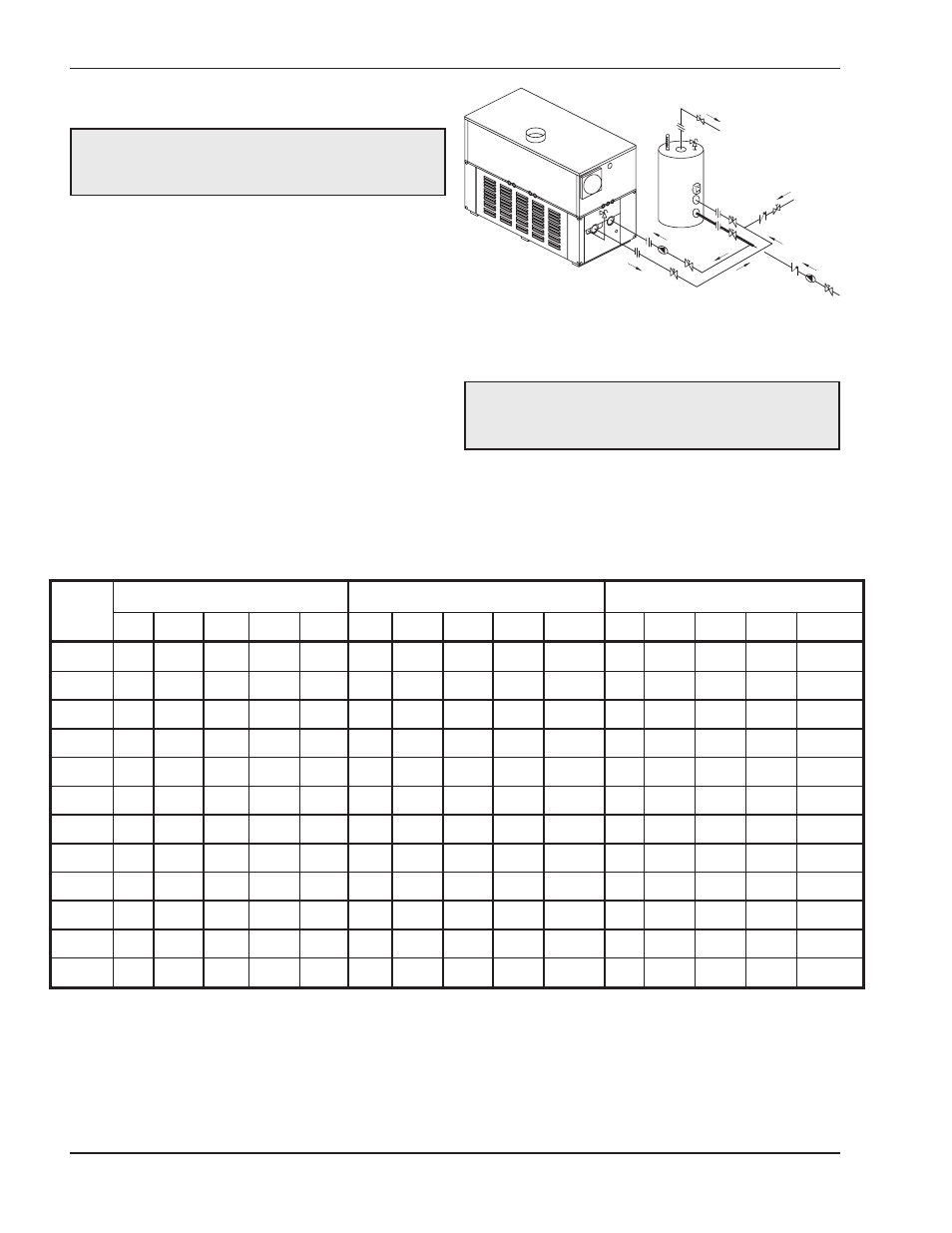
CAUTION: When this heater is used for both
potable water and space heating, observe the
following to ensure proper operation.
Fig. 13: Single Domestic Hot Water Heater and Storage
Tank
Table H: Domestic Water Heater Flow Rate Requirements
ΔT = Temperature rise, °F.
ΔP = Pressure drop through heat exchanger, ft.
SHL = System head loss, ft. (System head loss based on heater and tank placed no more than 5 ft apart and equivalent length pipe/fittings as fol-
lows: 2 in. tube = 25 ft; 2 1/2 in. tube = 80 ft.
gpm = Gallons per minute, flow rate.)
MTS = Minimum tubing size.
*Must utilize optional cupro-nickel tubes.
**With Hard Water (16-25 grains per gallon), the operating control must be set no higher than 130F for scale free operation. For operating temper-
atures above 130F, a water softener must be utilized.
Model
No.
Soft (0–4 grains per gallon)
Medium (5–15 grains per gallon)
Hard* (16–25** grains per gallon)
ΔT
gpm
ΔP
MTS
SHL
ΔT
gpm
ΔP
MTS
SHL
ΔT
gpm
ΔP
MTS
SHL
399B
17
40
2.0
2
4.4
13
52
3.4
2
7.2
8
90
10.0
2
20.5
499B
21
40
2.1
2
4.5
16
52
3.5
2
7.4
9
90
10.4
2
20.9
649B
28
40
2.2
2
4.6
20
55
4.1
2
8.4
12
90
10.8
2
21.3
749B
30
42
2.6
2
5.2
20
63
5.7
2
11.1
14
90
11.3
2
21.8
899B
30
51
3.9
2
7.6
20
76
8.4
2
16.1
17
90
11.7
2
22.2
989B
28
60
2.7
2 1/2
4.6
20
83
5.2
2 1/2
8.6
13
132
13.1
2 1/2
21.0
1259B
30
72
4.4
2 1/2
7.0
20
106
9.6
2 1/2
14.8
16
132
14.8
2 1/2
22.7
1529B
30
86
7.1
2 1/2
10.7
20
132
16.5
2 1/2
24.4
20
132
16.5
2 1/2
24.4
1799B
30
101
10.7
2 1/2
15.5
23
132
18.3
2 1/2
26.1
23
132
18.3
2 1/2
26.1
1999B
30
112
13.9
2 1/2
19.7
26
132
19.0
2 1/2
26.9
26
132
19.0
2 1/2
26.9
2069B
30
116
14.8
2 1/2
21.0
27
132
19.0
2 1/2
26.9
27
132
19.0
2 1/2
26.9
2339B
30
132
21.4
2 1/2
29.3
30
132
21.4
2 1/2
29.3
30
132
21.4
2 1/2
29.3
Gas Supply
Gas piping must have a sediment trap ahead of the
heater gas controls, and a manual shut-off valve lo-
cated outside the heater jacket. It is recommended
that a union be installed in the gas supply piping adja-
cent to the heater for servicing. A pounds-to-inches
DANGER: Make sure the gas on which the heater
will operate is the same type as specified on the
heater’s rating plate.