Chapter 3 operation, Front panel controls and indicators, 1 front panel controls and indicators – RAD Data comm MBE10-1D User Manual
Page 37: Lan ranger series configuration guide
Front Panel Controls and Indicators
3-1
Chapter 3
Operation
This chapter:
• Describes MBE front panel controls and indicators
• Provides basic operation instructions.
For in-depth information on configuration of MBE, see the
LAN RANger Series
Configuration Guide
.
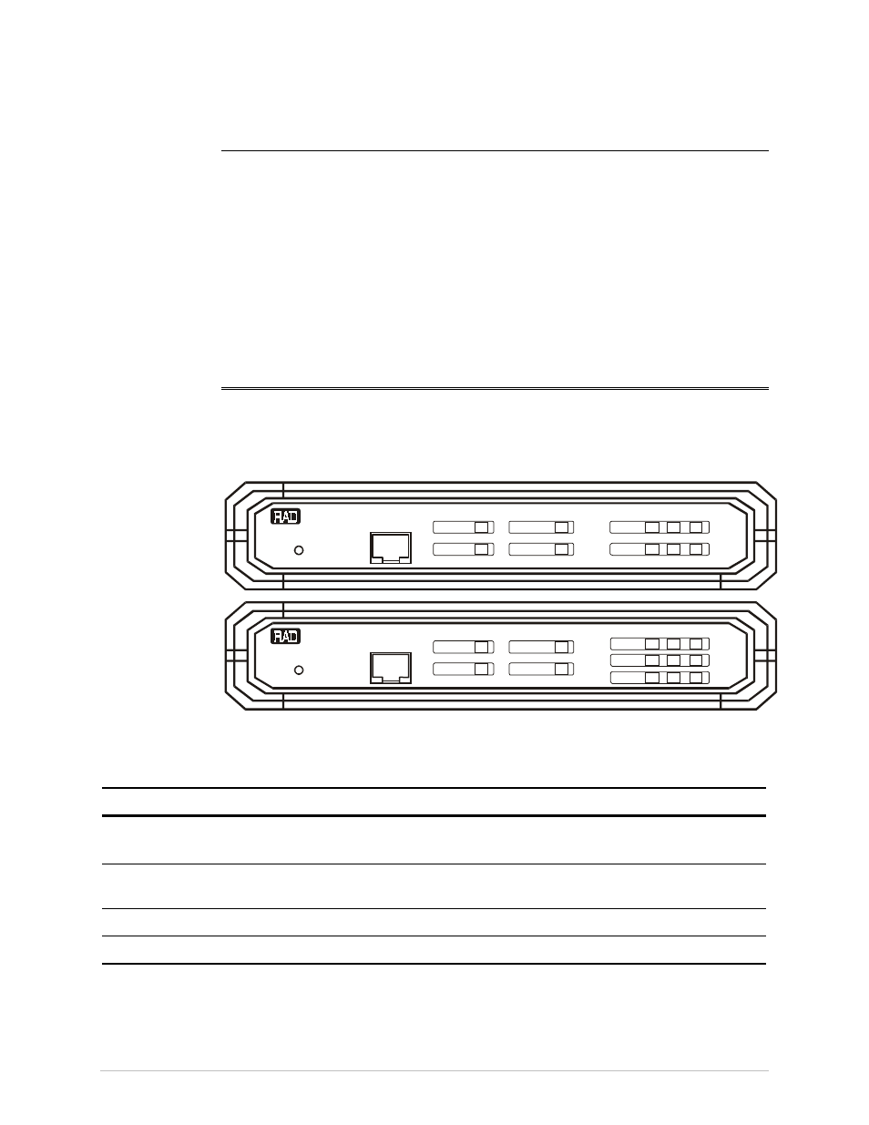
3.1 Front Panel Controls and Indicators
lists the functions of the MBE controls and indicators located on the front
panel.
RESET
RESET
CONTROL
CONTROL
MBE-8
MBE-8D
LAN
LAN
RAN
RAN
ger
ger
POWER
POWER
READY
READY
MAIN
LAN
LAN
TX
TX
RX
RX
ERR
ERR
REMOTE
REMOTE
LINK
LINK 1
LINK 2
MAIN
Figure 3-1. MBE Front Panel
Table 3-1. Front Panel Controls and Indicators
Controls and Indicators
Color
Function
RESET
Used to reset MBE. See the
LAN RANger Series
Configuration Guide
for software initiated reset
RJ45 SOCKET
(CONTROL)
Used for connection of terminal for diagnostics,
configuration, monitoring and downloading
POWER
Green
On when MBE is powered on
READY
Green
On continuously during normal operation
Order from: Cutter Networks
Ph:727-398-5252/Fax:727-397-9610
www.bestdatasource.com