System layout, L. drive, L. drive section – NEC 2060 User Manual
Page 26
9.
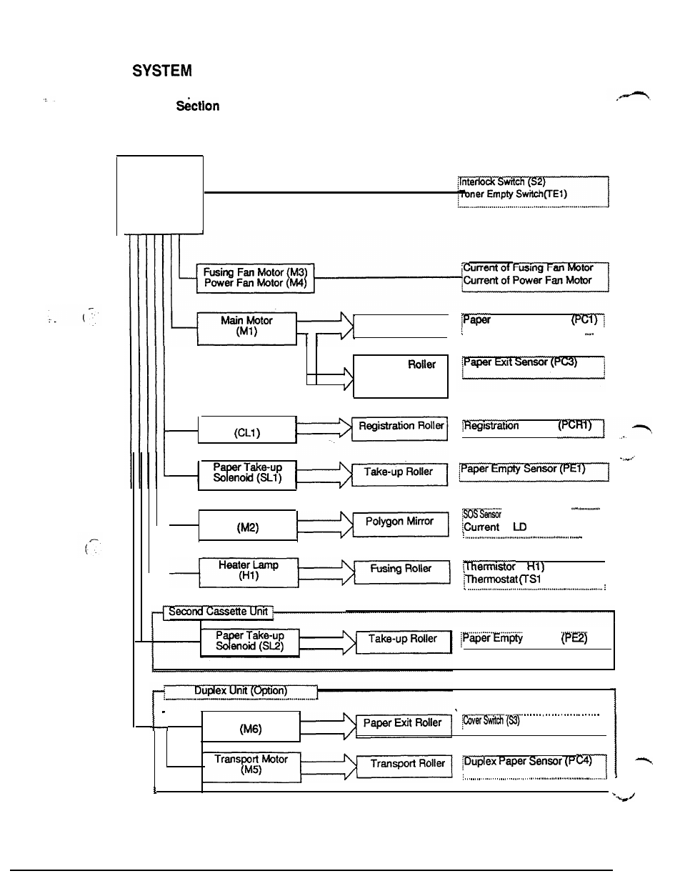
LAYOUT
9-1. Drive
: Mechanical Control and Sensor Layout
Main Control
Board
(PWB-A)
Transport Roller
Take-up Sensor
. . . . . . . . . . . . . . . . . . . . . . . . . . . . . . . . . . . . . . . . . . . . . . . . . . . . . . . .
. . . . .
Transfer
Fusing Roller
Paper Exit Roller
Registration Clutch
Sensor
Polygon Motor
. . . . . . . . . . . . . . . . . .
of
1
. . . .
(
I
)
............................. ..............
Sensor
Switchback Motor
B-10