Layout, Electrical component layout – NEC 2060 User Manual
Page 22
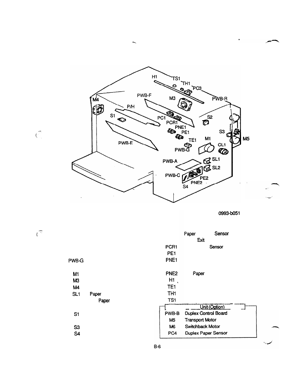
5. ELECTRICAL COMPONENT LAYOUT
M6
PWB-B
PC4
PWB-A
PWB-C
PWB-E
PWB-F
PWB-R
SL2
CL1
s2
Main control Board
2nd Cassette Unit Board
Power Unit
High Voltage Unit
Toner Empty Board
Resistor Board
Main Motor
Fusing Fan Motor
Power Fan Motor
Take-up Solenoid
2nd
Take-up Solenoid
Registration Clutch
Power Switch
Interlock Switch
Duplex Cover Switch
2nd Paper Size Switch
PC1
PC3
PE2
Take-up
Paper
Sensor
Registration
Paper Empty Sensor
Paper Near-empty Sensor
2nd Paper Empty Sensor
2nd
Near-empty Sensor
Heater Lamp
Toner Empty Sensor
Thermistor
Thermostat
Duplex
. . .._..“..... . .
. . . . .