Figure 3-6. ni pxi-8250 relay operation diagram – National Instruments Module NI PXI-8250 User Manual
Page 22
Chapter 3
Hardware Overview
3-6
ni.com
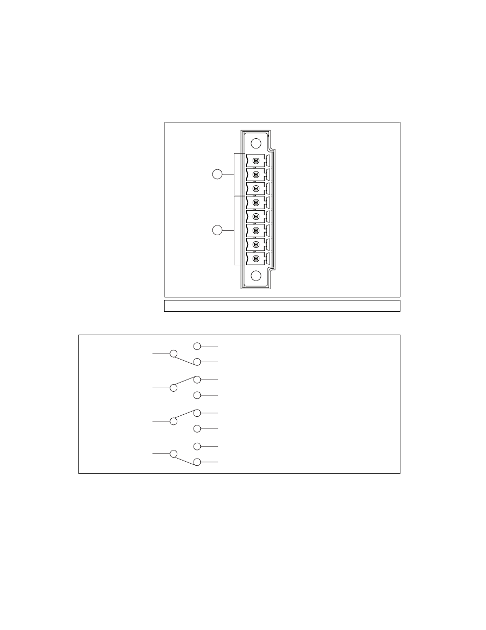
Figure 3-5 shows the layout of this connector.
Figure 3-5. NI PXI-8250 Front Panel Connector Pinout Diagram
Figure 3-6. NI PXI-8250 Relay Operation Diagram
1
Alert Relay Terminal Pins
2
Fused Power Output Terminal Pins
1
2
NO (Normally Open)
COM (Common)
NC (Normally Closed)
5V
3.3V
12V
-12V
GND (Ground)
NO (Normally Open)
COM (Common)
NC (Normally Closed)
Chassis off
(or power off)
NO (Normally Open)
COM (Common)
NC (Normally Closed)
Initial power up
of chassis (7 seconds)
NO (Normally Open)
COM (Common)
NC (Normally Closed)
Chassis on
without error(s)
NO (Normally Open)
COM (Common)
NC (Normally Closed)
Chassis on
with error(s)
See also other documents in the category National Instruments Hardware:
- Instrument Driver NI-DMM (12 pages)
- 24-Bit Half/Full-Bridge Analog Input Module NI 9237 (36 pages)
- NI PXIe-8105 (76 pages)
- PXI NI 5401 (60 pages)
- Fieldpoint CFP-2210 (38 pages)
- NI 781xR (48 pages)
- NI 6233 (180 pages)
- 6508 PCI-DIO-96 (93 pages)
- PXI/CompactPCI Embedded Computer NI PXI-8108 (83 pages)
- NI 9233 (34 pages)
- NI USB-9219 (25 pages)
- GPIB-PC (262 pages)
- cFP-RTD-122 (15 pages)
- USB device 625x (23 pages)
- Isolated Analog Input Modules SCC-AI01 (18 pages)
- NI PCI-6111 (118 pages)
- NI USB-6008 (32 pages)
- PC-DIO-24 (75 pages)
- NI 9474 (31 pages)
- NI 6013 (109 pages)
- PXI-1428 (46 pages)
- NI PCI-5911 (51 pages)
- 2 SD Card Memory Module NI 9802 (16 pages)
- cFP-20xx (24 pages)
- NI USB-9234 (23 pages)
- NI 9871 (24 pages)
- Interface Device NI PCI-1426 (35 pages)
- AT E Series (184 pages)
- 9211A (19 pages)
- 8330 Series (30 pages)
- NI PXIe-8360 (40 pages)
- Deterministic Ethernet Expansion Chassis NI 9144 (65 pages)
- NI 6509 (23 pages)
- NI MATRIXx Xmath (127 pages)
- NI 9481 (23 pages)
- Monochrome Image Acquisition Device NI 1410 (34 pages)
- VXI-1394 (74 pages)
- NI PXI-8104 (69 pages)
- NI 9235 (38 pages)
- 370620B-01 (17 pages)
- FP-RTD-124 (15 pages)
- VXI-USB (61 pages)
- NI PCI-8254R (45 pages)
- Interface Device NI PCI-8254R (16 pages)