Nortel Networks COMMUNICATION SERVER 1000 NN43021-110 User Manual
Page 38
38
System architecture
Core/Net modules diagnose faults in field-replaceable units for all core
hardware, including cables. In case of a failure, a message appears on the
system terminal and on the LCD of the faceplate of the utility card.
Core to Core Ethernet connection (LAN1 to LAN2) between the CP PIV
cards allows memory shadowing and dual-CPU operation.
The cCNI Transition cards connect the Core module cards to the 3PE
cards in the Network modules. Each Core module contains between
one and four cCNI cards. Since each cCNI card can connect up to two
Network groups, each Core is connected to a minimum of two groups
and a maximum of eight groups. The number of cCNI cards in a system
depends on the number of Network groups in that system. The first cCNI
card that connects to Network group 0 and group 1 is installed in slot c9 of
each Core/Net module. Each additional cCNI card is installed in ascending
order from slots c10 to c12.
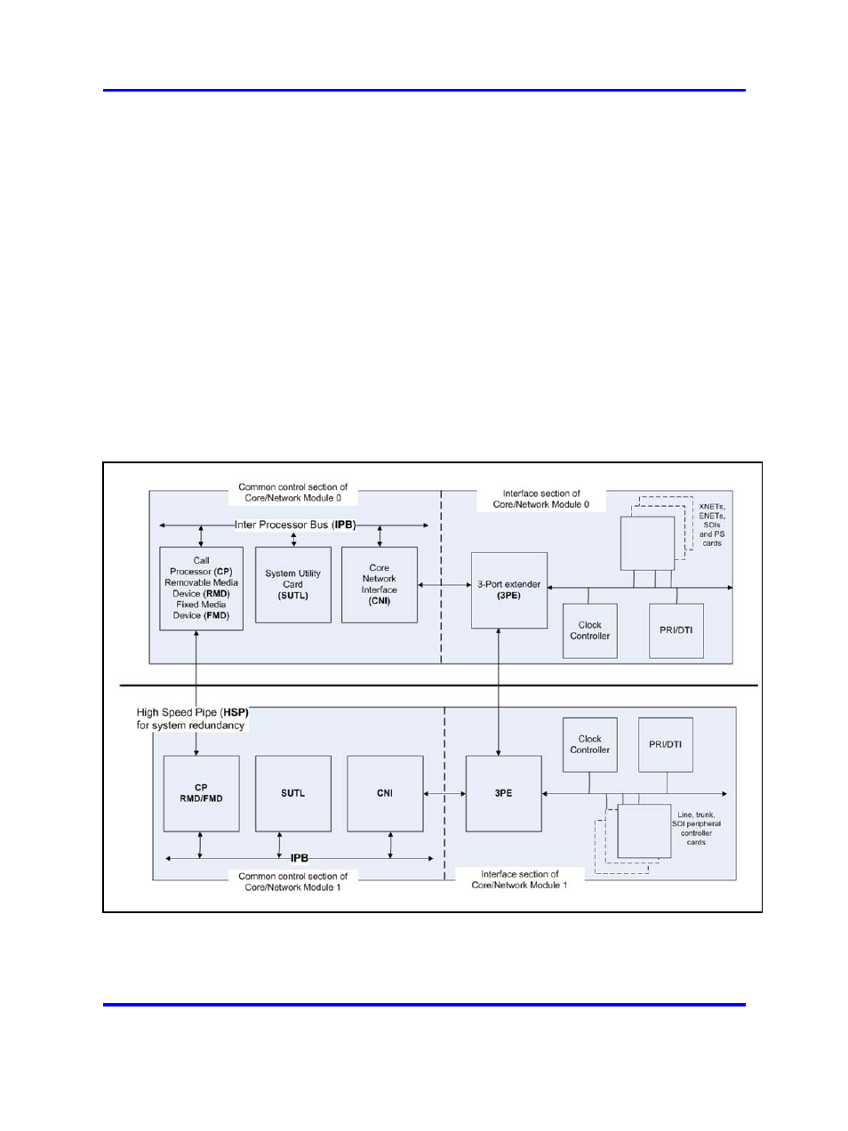
Figure 14
CS 1000M SGand Meridian 1 PBX 61C CP PIVcore complex
Nortel Communication Server 1000
Communication Server 1000M and Meridian 1 Large System Overview
NN43021-110
02.05
Standard
30 September 2008
Copyright © 2003-2008 Nortel Networks
.