Blower replacement – Napoleon Fireplaces PARK AVENUE GD82PT User Manual
Page 18
18
W415-0536 / B / 07.20.06
BLOWER
MOUNTING
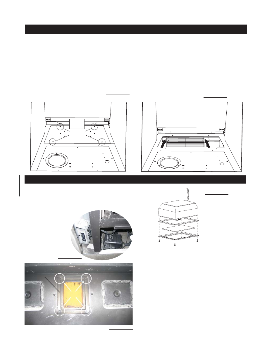
PLATE
REMOVE 4 SCREWS
BLOWER REPLACEMENT
The Napoleon PARK AVENUE comes equipped with a heat
circulating blower. The blower is pre-wired and is controlled by
the remote control supplied with the unit. For control details,
see operation. Pg. 22.
Drywall dust will penetrate into the blower bearings, caus-
ing irreparable damage. Care must be taken to prevent
drywall dust from coming into contact with the blower or
its compartment. Any damage resulting from this condi-
tion is not covered by the warranty policy.
1. Turn off the power to the fi replace.
2. Turn off the gas valve.
3. Remove the glass door, logs, rear log supports, brick
panels, air defl ector, burner assy, panel support, panel sup-
port bracket.
4. The blower mounting plate can now be removed. Remove
the four screws that secure the plate to the fi rebox base.
5. The blower is secured to the fi rebox. Disconnect the wire
connectors before attempting to remove the blower from the
fi rebox.
6. Remove the two screws securing the blower and lift through
blower access opening.
FIGURE 37
REMOVE 2 SCREWS
Your PARK AVENUE comes equipped with our “Night Light”.
The light has been pre-wired and is controlled from the
remote control.
If in the event the lamp or lens needs to be replaced, follow
the instructions below.
Unplug the wireharness
/ transformer from the
junction box inside the
fi replace.
NIGHT LIGHT REPLACEMENT
SCREWS
LENSE
FRAME
FIREBOX TOP
FIGURE 40
Remove the four screws that secure the lens frame.
This frame retains the glass lens. The lamp can now be
accessed.
Note: Do not handle the lamp (bulb) with bare fi ngers,
protect with a clean dry cloth.
The lamp will pull straight out of the socket. Replace with
Wolf Steel parts only, as lamp and lens are special “high
temperature” products.
When re-installing, ensure integrity of gasket seal.
THE FIREBOX MUST BE SEALED.
Over tightening the screws could break the lens.
“Light Leakage” from the upper area may be observed.
The holes in the lamp housing are necessary for
ventilation and must not be covered.
FIGURE 39
FIGURE 41
AMBER SIDE UP
GASKET
LENSE
FRAME
Note: When re-installing the replace-
ment blower, it will be necessary to
replace the gasket (W290-0104) on
the blower mounting plate.
FIGURE 38