Electrical connection, Auxiliary device fan l2 l1 [hot] tp th, Mantle clearances – Napoleon Fireplaces PARK AVENUE GD82PT User Manual
Page 16: Hard wiring connection schematic, Firestop spacer, Spacer stand off top of fireplace opening, Top of unit
16
W415-0536 / B / 07.20.06
FIGURE 32
MANTLE CLEARANCES
0
3 4
7
8
9
11
13
1 2
5 6
7
10
12
H
E
I
G
H
T
M
A
N
T
L
E
MANTLE WIDTH
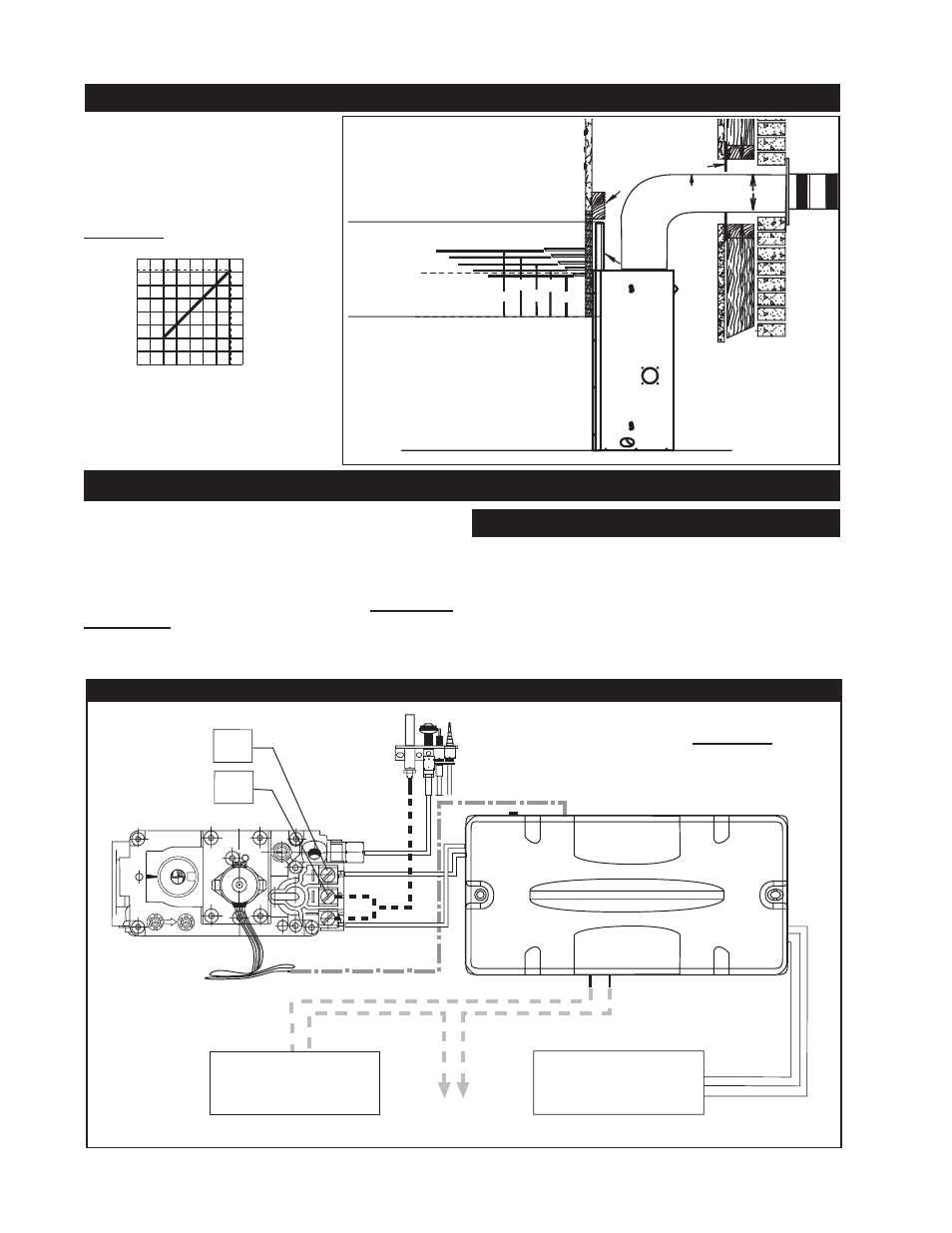
Combustible mantle clearance
can vary according to the man-
tle depth. Use the graph to
help evaluate the clearance
needed.
Do NOT use the fi replace if any part has been under
water.
Call a qualified service technician IMMEDIATELY to
have the fi replace inspected for damage to the electri-
cal circuit.
If access to the control area is necessary BEFORE IN-
STALLATION, remove the access panel.
The access panel must be re-installed before operating
the unit.
It is necessary to hard wire this fi replace.
Permanently framing the fi replace with an enclosure, requires
the fi replace junction box to be hardwired.
This fi replace must be electrically connected and grounded in
accordance with local codes. In the absence of local codes,
use the current CSA C22.1 CANADIAN ELECTRICAL CODE
in Canada or the ANSI/NFPA 70-1996 NATIONAL ELECTRI-
CAL CODE in the United States.
ELECTRICAL CONNECTION
HARD WIRING CONNECTION
SCHEMATIC
IN
OUT
OF
F
P
IL
O
T
ON
AUXILIARY
DEVICE
FAN
L2
L1
[HOT]
TP
TH
AUX
FA
N
LINE
VA
LV
E
MOTOR A
UT
O MAN
GAS
FIGURE 33
STUD
2"
FIRESTOP
SPACER
2"
SPACER
STAND OFF
TOP OF
FIREPLACE
OPENING
8"
9"
10"
11"
5"4"
3" 2"
6" MANTLE
TOP OF
UNIT
INSULATION
SLEEVE
1" GAP FROM INSULATION SLEEVE
2" GAP FROM VENTING
12"