Analog i/o connector signal descriptions, Figure 4-1. analog pin connections, Analog i/o connector signal descriptions -2 – National Instruments PCI-4452 User Manual
Page 32: Figure 4-1, Analog pin connections -2
Chapter 4
Signal Connections
PCI-4451/4452 User Manual
4-2
©
National Instruments Corporation
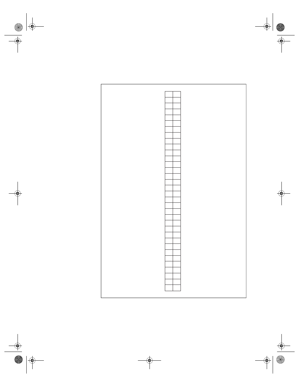
Analog I/O Connector Signal Descriptions
Figure 4-1 shows the analog pin connections for the PCI-4451/4452.
Figure 4-1. Analog Pin Connections
GND
+5 V
NC
NC
NC
NC
NC
-DAC1 OUT
NC
-DAC0 OUT
NC
NC
NC
NC
NC
NC
NC
NC
NC
NC
NC
NC
NC
NC
NC
NC
NC
-ACH3
NC
ACH2-
NC
-ACH1
NC
-ACH0
GND
NC
NC
NC
GND
+DAC1 OUT
GND
+5 V
NC
+DAC0 OUT
NC
NC
NC
NC
NC
NC
NC
NC
NC
NC
NC
NC
NC
NC
NC
NC
GND
+ACH3
GND
+ACH2
GND
+ACH1
GND
+ACH0
1
35
2
36
3
37
4
38
5
39
6
40
7
41
8
42
9
43
10 44
11 45
12 46
13 47
14 48
15 49
16 50
17 51
18 52
19 53
20 54
21 55
22 56
23 57
24 58
25 59
26 60
27 61
28 62
29 63
30 64
31 65
32 66
33 67
34 68
User.book Page 2 Tuesday, April 14, 1998 10:20 AM
This manual is related to the following products: