Figure 37. retriggerable single pulse generation, Retriggerable single pulse generation – National Instruments Eight-slot USB Chassis NI cDAQ-9172 User Manual
Page 60
NI cDAQ-9172 User Guide and Specifications
60
ni.com
Figure 36 shows a generation of a pulse with a pulse delay of four and a
pulse width of three (using the rising edge of Source).
Figure 36. Single Pulse Generation with Start Trigger
Retriggerable Single Pulse Generation
The counter can output a single pulse in response to each pulse on a
hardware Start Trigger signal. The pulses appear on the Counter n Internal
Output signal of the counter.
You can route the Start Trigger signal to the Gate input of the counter. You
can specify a delay from the Start Trigger to the beginning of each pulse.
You also can specify the pulse width. The delay and pulse width are
measured in terms of a number of active edges of the Source input.
The counter ignores the Gate input while a pulse generation is in progress.
After the pulse generation is finished, the counter waits for another Start
Trigger signal to begin another pulse generation.
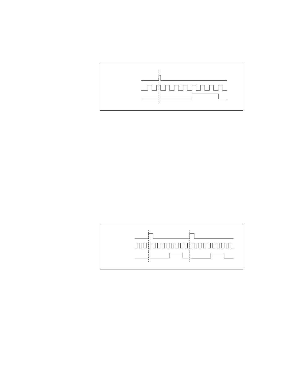
Figure 37 shows a generation of two pulses with a pulse delay of five and a
pulse width of three (using the rising edge of Source).
Figure 37. Retriggerable Single Pulse Generation
For information on connecting counter signals, refer to the
section.
SOURCE
GATE
(Start Trigger)
OUT
SOURCE
GATE
(Start Trigger)
OUT