Digital i/o signal connections, Digital i/o signal connections -7 – National Instruments SCXI-1161 User Manual
Page 32
Chapter 3
Signal Connections
© National Instruments Corporation
3-7
All other pins are not connected.
Digital I/O Signal Connections
When you configure the SCXI-1161 for an MIO-type board, the digital
I/O signals of the SCXI-1161 match the digital I/O lines of the
MIO-type board. When you use the SCXI-1161 with an SCXI-1341,
SCXI-1342, or SCXI-1344 cable assembly, the SCXI-1161 signals
match the digital lines of the Lab-NB/Lab-PC/Lab-PC+ boards, the
PC-LPM-16/PnP board, and the Lab-LC board, respectively. When you
configure the SCXI-1161 for a DIO-type board, the digital I/O signals
of the SCXI-1161 match the digital I/O lines of the DIO-24 and DIO-96
boards. When you use the SCXI-1161 with an SCXI-1348 cable
assembly, the SCXI-1161 signals match the digital lines of the DIO-32F
board.
29
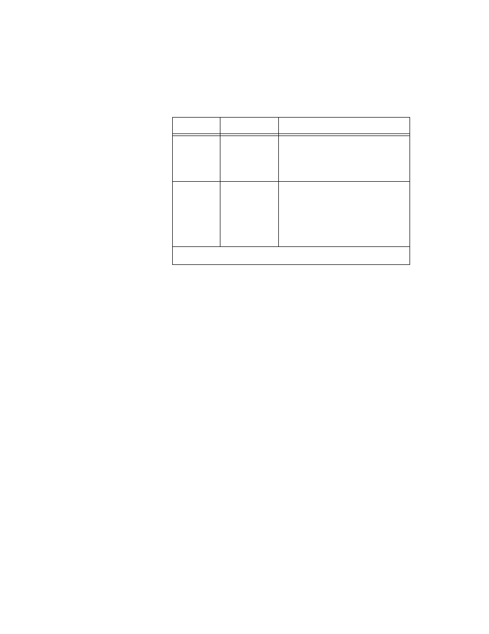
SLOT0SEL*
Slot 0 Select—Taps into the
SCXIbus INTR* line to indicate
whether the information on MOSI is
sent to a module or to Slot 0.
31 or 37
SERCLK
Serial Clock—Taps into the
SCXIbus SPICLK line to clock the
data on the MOSI and MISO lines.
Pin 31 is for DIO-type boards. Pin 37
is for MIO-type boards. Jumper W4
selects the pin.
* Indicates active low.
Table 3-3. Rear Signal Connector Signal Descriptions (Continued)
Pin
Signal Name
Description