Figure 1-7. nvs 6 electrical diagram – Newcon Optik NVS 6 User Manual
Page 15
14
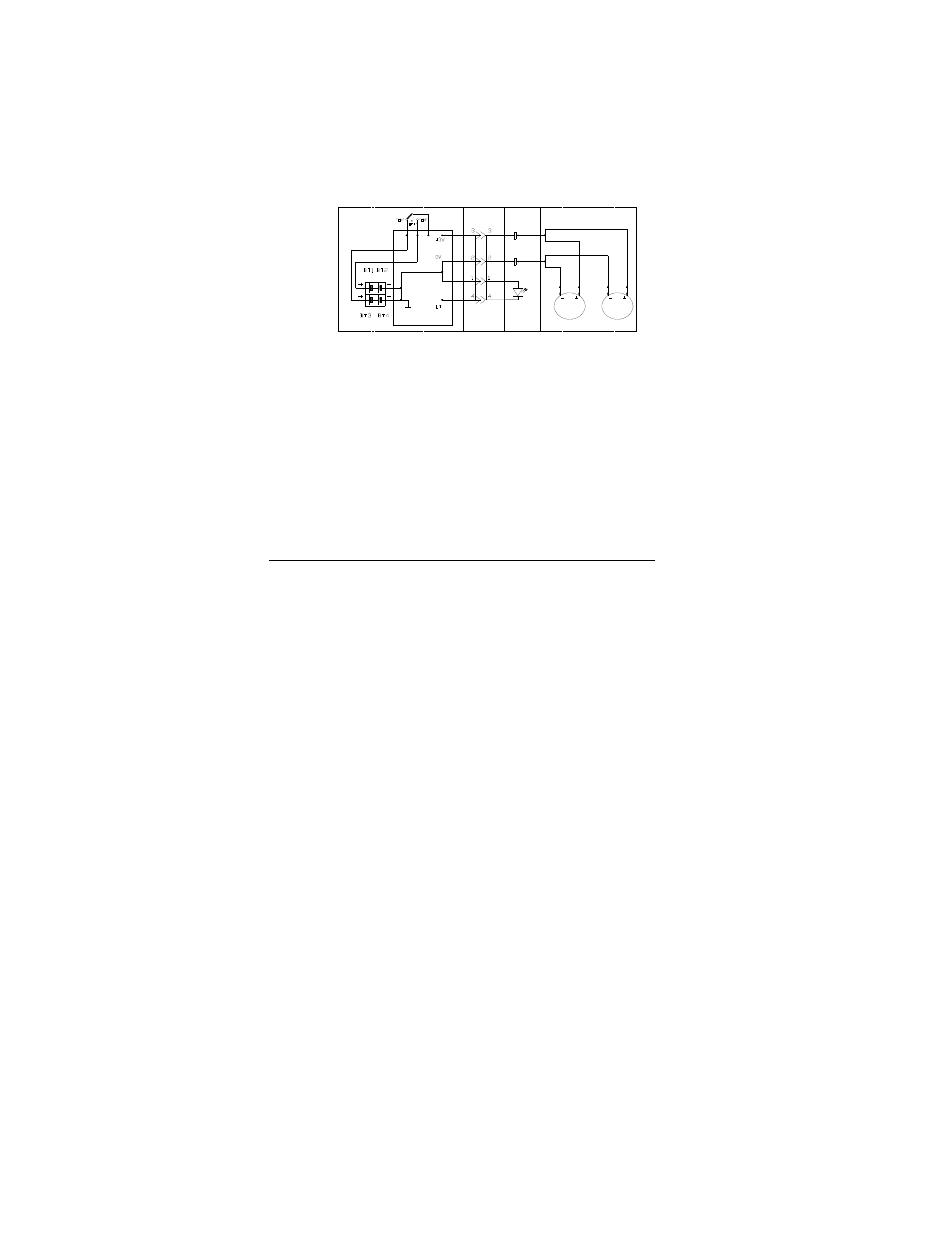
1.6.3 Electronic circuit
The electronic circuit regulates the direct current voltage from
the batteries to the image intensifier assemblies, as required. It
also monitors the output voltage of the batteries and turns on a
low-battery indicator when the battery's life is approximately 30
minutes (2.1 Vdc).
1.6.4 Image intensifier's power supply function
The power supply inside the image intensifier assembly (refer to
Fig.1-6) converts the 3.0 volts from the power pack to the
applicable voltages, which provide the optimal conditions for
operating the image intensifier. The power supply also provides
automatic brightness control (ABC) and bright source protection
(BSP) under high light conditions.
1.5V x 2
1.5V x 2
IM AGE INTENSIFIERS
ELECTRO NIC C IRCU IT
"LO W -BATTER Y"
BINO CULAR ASSEMBLY
POW ER PACK
PO W ER SW ITCH
POW ER
CABLE
RED
LED
M OUNT
ASSEM BLY
Figure 1-7. NVS 6 electrical diagram