R1005050 connector, Figure 4. r1005050 connector pinout – National Instruments NI 6509 User Manual
Page 13
© National Instruments Corporation
13
NI 6509 User Guide and Specifications
R1005050 Connector
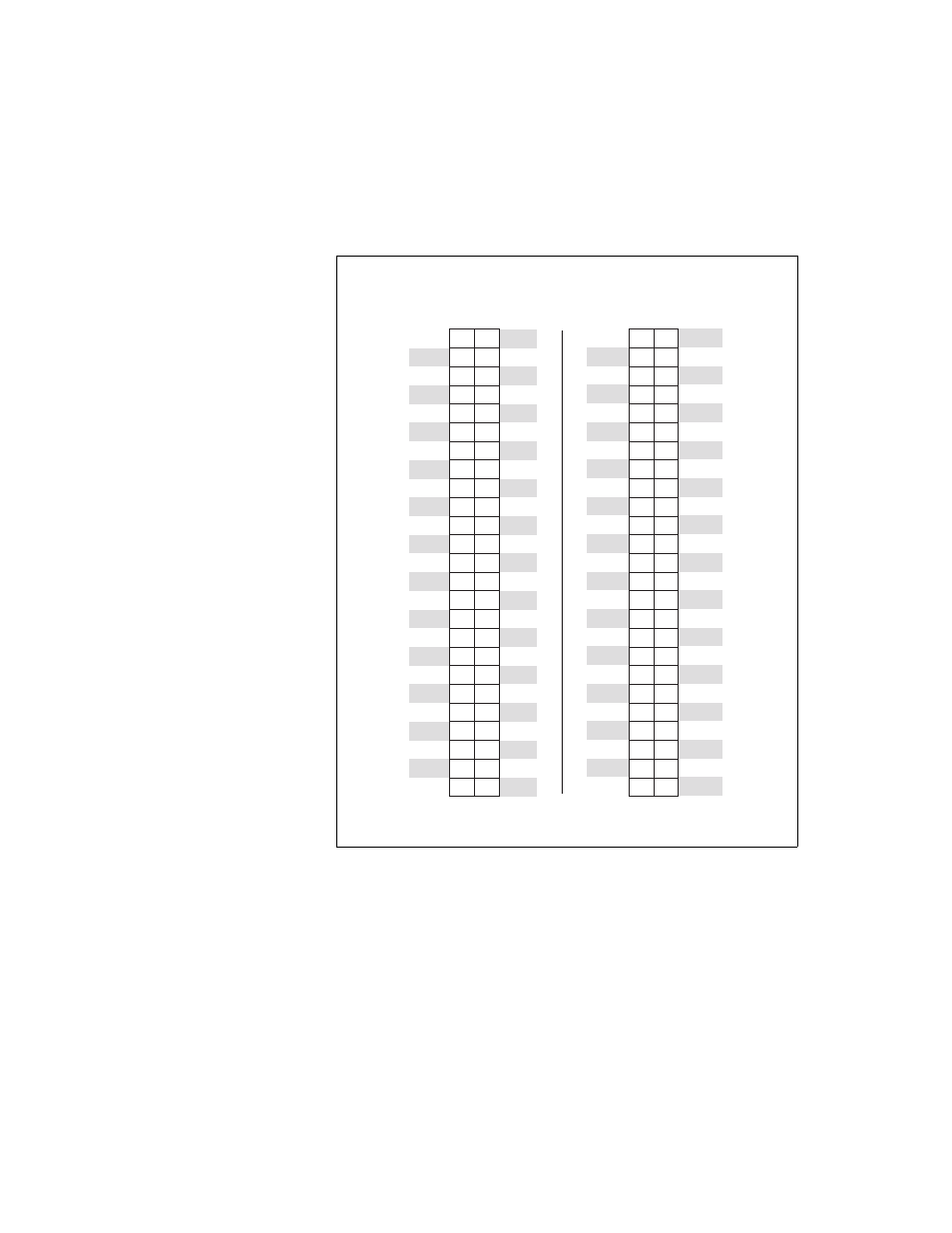
Figure 4 shows the pin assignments for the R1005050 cable when
connecting to the NI 6509 device. The naming convention for each pin is
PX.Y, where X is the port (P) number, and Y is the line number or name.
Figure 4. R1005050 Connector Pinout
Refer to the
section for information about the signals
available on this connector.
+5 V
P0.0
P0.1
P0.2
P0.3
P0.4
P0.5
P0.6
P0.7
P1.0
P1.1
P1.2
P1.3
P1.4
P1.5
P1.6
P1.7
P2.0
P2.1
P2.2
P2.3
P2.4
P2.5
P2.6
P2.7
GND
P3.1
P3.2
P3.4
P3.5
P3.6
P3.7
P3.0
P3.3
P4.0
P4.1
P4.2
P4.3
P4.4
P4.5
P4.6
P4.7
P5.0
P5.1
P5.2
P5.3
P5.4
P5.5
P5.6
P5.7
49 50
47 48
45 46
43 44
41 42
39 40
37 38
35 36
33 34
31 32
29 30
27 28
25 26
23 24
21 22
19 20
17 18
15 16
13 14
11 12
9
10
7
8
5
6
3
4
1
2
Positions 1 through 50
+5 V
P6.0
P6.1
P6.2
P6.3
P6.4
P6.5
P6.6
P6.7
P7.0
P7.1
P7.2
P7.3
P7.4
P7.5
P7.6
P7.7
P8.0
P8.1
P8.2
P8.3
P8.4
P8.5
P8.6
P8.7
GND
P9.1
P9.2
P9.4
P9.5
P9.6
P9.7
P9.0
P9.3
P10.0
P10.1
P10.2
P10.3
P10.4
P10.5
P10.6
P10.7
P11.0
P11.1
P11.2
P11.3
P11.4
P11.5
P11.6
P11.7
49 50
47 48
45 46
43 44
41 42
39 40
37 38
35 36
33 34
31 32
29 30
27 28
25 26
23 24
21 22
19 20
17 18
15 16
13 14
11 12
9
10
7
8
5
6
3
4
1
2
Positions 51 through 100