Figure 3. sh100-100-f connector pinout, Gure 3 – National Instruments NI 6509 User Manual
Page 12
NI 6509 User Guide and Specifications
12
ni.com
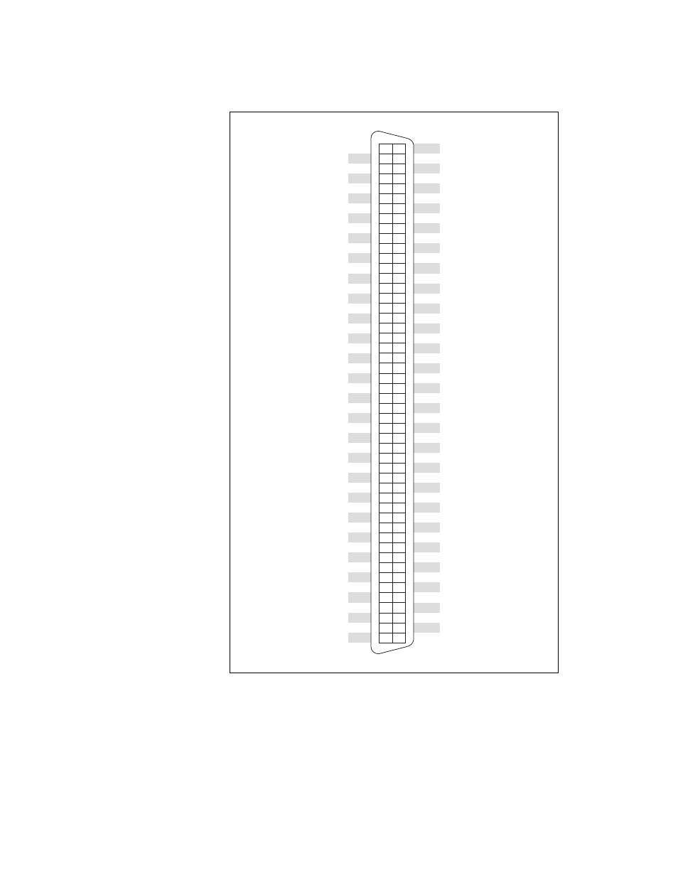
Figure 3. SH100-100-F Connector Pinout
Refer to the
section for information about the signals
available on this connector.
+5 V
P3.0
P0.0
P3.1
P0.1
P3.2
P0.2
P3.3
P0.3
P3.4
P0.4
P3.5
P0.5
P3.6
P0.6
P3.7
P0.7
P4.0
P1.0
P4.1
P1.1
P4.2
P1.2
P4.3
P1.3
P4.4
P1.4
P4.5
P1.5
P4.6
P1.6
P4.7
P1.7
P5.0
P2.0
P5.1
P2.1
P5.2
P2.2
P5.3
P2.3
P5.4
P2.4
P5.5
P2.5
P5.6
P2.6
P5.7
+5 V
P9.0
P6.0
P9.1
P6.1
P9.2
P6.2
P9.3
P6.3
P9.4
P6.4
P9.5
P6.5
P9.6
P6.6
P9.7
P6.7
P10.0
P7.0
P10.1
P7.1
P10.2
P7.2
P10.3
P7.3
P10.4
P7.4
P10.5
P7.5
P10.6
P7.6
P10.7
P7.7
P11.0
P8.0
P11.1
P8.1
P11.2
P8.2
P11.3
P8.3
P11.4
P8.4
P11.5
P8.5
P11.6
P8.6
P11.7
GND
P2.7
25
24
23
22
21
20
19
18
17
16
15
14
13
12
11
10
9
8
7
6
5
4
3
2
1
75
74
73
72
71
70
69
68
67
66
65
64
63
62
61
60
59
58
57
56
55
54
53
52
51
50
49
48
47
46
45
44
43
42
41
40
39
38
37
36
35
34
33
32
31
30
29
28
27
26
100
99
98
97
96
95
94
93
92
91
90
89
88
87
86
85
84
83
82
81
80
79
78
77
76
GND
P8.7
- Instrument Driver NI-DMM (12 pages)
- 24-Bit Half/Full-Bridge Analog Input Module NI 9237 (36 pages)
- NI PXIe-8105 (76 pages)
- PXI NI 5401 (60 pages)
- Fieldpoint CFP-2210 (38 pages)
- NI 781xR (48 pages)
- NI 6233 (180 pages)
- 6508 PCI-DIO-96 (93 pages)
- PXI/CompactPCI Embedded Computer NI PXI-8108 (83 pages)
- NI 9233 (34 pages)
- NI USB-9219 (25 pages)
- GPIB-PC (262 pages)
- cFP-RTD-122 (15 pages)
- USB device 625x (23 pages)
- Isolated Analog Input Modules SCC-AI01 (18 pages)
- NI PCI-6111 (118 pages)
- NI USB-6008 (32 pages)
- PC-DIO-24 (75 pages)
- NI 9474 (31 pages)
- NI 6013 (109 pages)
- PXI-1428 (46 pages)
- NI PCI-5911 (51 pages)
- 2 SD Card Memory Module NI 9802 (16 pages)
- cFP-20xx (24 pages)
- NI USB-9234 (23 pages)
- NI 9871 (24 pages)
- Interface Device NI PCI-1426 (35 pages)
- AT E Series (184 pages)
- 9211A (19 pages)
- Module NI PXI-8250 (39 pages)
- 8330 Series (30 pages)
- NI PXIe-8360 (40 pages)
- Deterministic Ethernet Expansion Chassis NI 9144 (65 pages)
- NI MATRIXx Xmath (127 pages)
- NI 9481 (23 pages)
- Monochrome Image Acquisition Device NI 1410 (34 pages)
- VXI-1394 (74 pages)
- NI PXI-8104 (69 pages)
- NI 9235 (38 pages)
- 370620B-01 (17 pages)
- FP-RTD-124 (15 pages)
- VXI-USB (61 pages)
- NI PCI-8254R (45 pages)
- Interface Device NI PCI-8254R (16 pages)