Figure 4-1. single-ended switch configuration, Figure 4-2. differential switch configuration, Special considerations – National Instruments SCB-68 User Manual
Page 45: Special considerations -3
Chapter 4
Using Thermocouples
© National Instruments Corporation
4-3
SCB-68 Shielded Connector Block User Manual
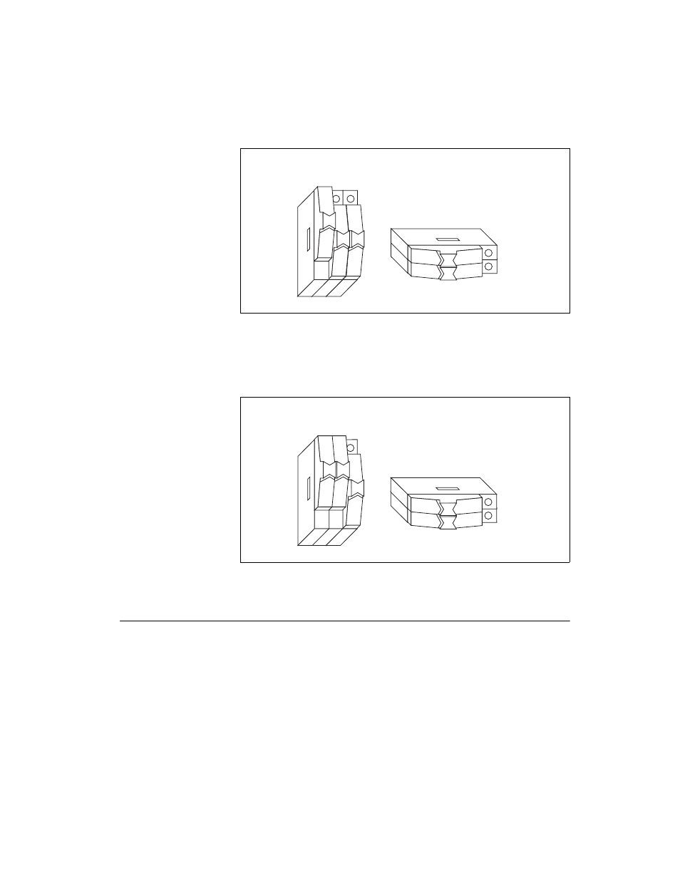
Figure 4-1. Single-Ended Switch Configuration
For differential operation, connect differential analog channel 0 to the
temperature sensor by switching S5 and S4 to the up position, as shown in
Figure 4-2.
Figure 4-2. Differential Switch Configuration
Special Considerations
To connect a high-value resistor between the positive input and +5V, refer
to the
Accuracy and Resolution Considerations
section of Chapter 5,
Adding Components for Special Functions
To reduce noise by connecting a lowpass filter to the analog inputs of the
SCB-68, refer to the
section of Chapter 5,
Components for Special Functions
S1
S2
S5 S4 S3
Signal Conditioning
Circuitry Power (On)
Temperature Sensor
S1
S2
S5 S4 S3
Signal Conditioning
Circuitry Power (On)
Temperature Sensor
- Instrument Driver NI-DMM (12 pages)
- 24-Bit Half/Full-Bridge Analog Input Module NI 9237 (36 pages)
- NI PXIe-8105 (76 pages)
- PXI NI 5401 (60 pages)
- Fieldpoint CFP-2210 (38 pages)
- NI 781xR (48 pages)
- NI 6233 (180 pages)
- 6508 PCI-DIO-96 (93 pages)
- PXI/CompactPCI Embedded Computer NI PXI-8108 (83 pages)
- NI 9233 (34 pages)
- NI USB-9219 (25 pages)
- GPIB-PC (262 pages)
- cFP-RTD-122 (15 pages)
- USB device 625x (23 pages)
- Isolated Analog Input Modules SCC-AI01 (18 pages)
- NI PCI-6111 (118 pages)
- NI USB-6008 (32 pages)
- PC-DIO-24 (75 pages)
- NI 9474 (31 pages)
- NI 6013 (109 pages)
- PXI-1428 (46 pages)
- NI PCI-5911 (51 pages)
- 2 SD Card Memory Module NI 9802 (16 pages)
- cFP-20xx (24 pages)
- NI USB-9234 (23 pages)
- NI 9871 (24 pages)
- Interface Device NI PCI-1426 (35 pages)
- AT E Series (184 pages)
- 9211A (19 pages)
- Module NI PXI-8250 (39 pages)
- 8330 Series (30 pages)
- NI PXIe-8360 (40 pages)
- Deterministic Ethernet Expansion Chassis NI 9144 (65 pages)
- NI 6509 (23 pages)
- NI MATRIXx Xmath (127 pages)
- NI 9481 (23 pages)
- Monochrome Image Acquisition Device NI 1410 (34 pages)
- VXI-1394 (74 pages)
- NI PXI-8104 (69 pages)
- NI 9235 (38 pages)
- 370620B-01 (17 pages)
- FP-RTD-124 (15 pages)
- VXI-USB (61 pages)
- NI PCI-8254R (45 pages)
- Interface Device NI PCI-8254R (16 pages)