About connectors – Panasonic WJ-ND400 User Manual
Page 33
About Connectors
33
Turning [On] the external switch starts emergency recording.
Emergency recording operations differ depending on the [Emergency rec.] settings accessed through the Setup menu (refer to Setup Instructions
(PDF file)).
Turning [On] the external switch, records by switching the program.
Set the recording program in [Time table setup (Ext.)] under [Time table] on the settings menu (refer to Setup Instructions (PDF file)).
When settings menu - [Basic] - [Time & date] - [Auto adjustment time] is set to [Master]
[Time Adjust Output] is available and the time on other devices is synchronized with the recorder.
When the time set under [Activation time] is reached, a signal is output from the Time adjustment input/output (pin no. 20).
22
Alarm
suspension
input
The state of alarm suspension is assumed
according to the signal input.
Non-voltage make contact input 5V
pull-up 150 k
Ω
23
Outage detection input
Start of outage processing according to the signal
input.
24
External recording mode
switching input
Changeover to the external recording mode
25
+5 V output
+5 V output
200 mA max.
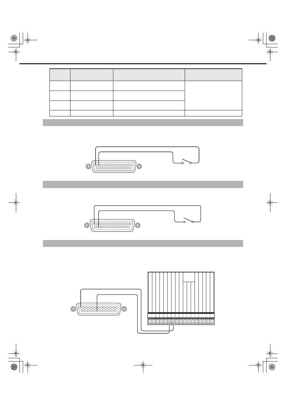
Connectivity for Emergency Recording
Connectivity for Switching to External Recording
Auto Adjustment Time Function Connection 1
Pin
Number
Name
Description of Operation
Remarks
(Signal ground)
(Emergency recording input)
External switch
13
12
ALARM/CONTROL
13
24
(External recording mode switching)
(Signal ground)
External switch
ALARM/CONTROL
20
13
(Signal ground)
(Time adjustment output)
Front panel
LED monitor
output
Ser
ies recording o
u
tp
u
t
Time adj
u
stment o
u
tp
u
t
T
emper
at
u
re w
ar
ning o
u
tp
u
t
System error o
u
tp
u
t
B
u
zz
er o
u
tp
u
t
Disk
Recording
Alar
m recording
Alar
m restore o
u
tp
u
t
Alar
m o
u
tp
u
t
Signal g
ro
u
nd
Time adj
u
stment inp
u
t
Ser
ies recording inp
u
t
Alar
m reset inp
u
t
Alar
m Inp
u
t
Sensor inp
u
t
Signal g
ro
u
nd
Terminal for other devices
ALARM/CONTROL
ND400_Basic.book 33 ページ 2008年4月8日 火曜日 午後3時59分