Pager, Pc/printer (via rs-232c) – Philips KX-TAW848 User Manual
Page 96
2.9 Connection of Peripherals
96
Installation Manual
Pager
Only one paging device (user-supplied) can be connected to the PBX.
CAUTION
An External Paging Jack is a SELV port and should only be connected to an approved SELV device.
PC/Printer (via RS-232C)
The PBX is equipped with an RS-232C interface. This interface provides communication between the PBX
and the user-supplied devices such as PC or line printers. The RS-232C port is used for system
programming, SMDR, diagnostics and external system database storage (save/load) functions.
When using special accessories such as cable, the user should use those specified in this installation
manual to comply with the limits for a Class B digital device pursuant to the FCC Rules.
Note
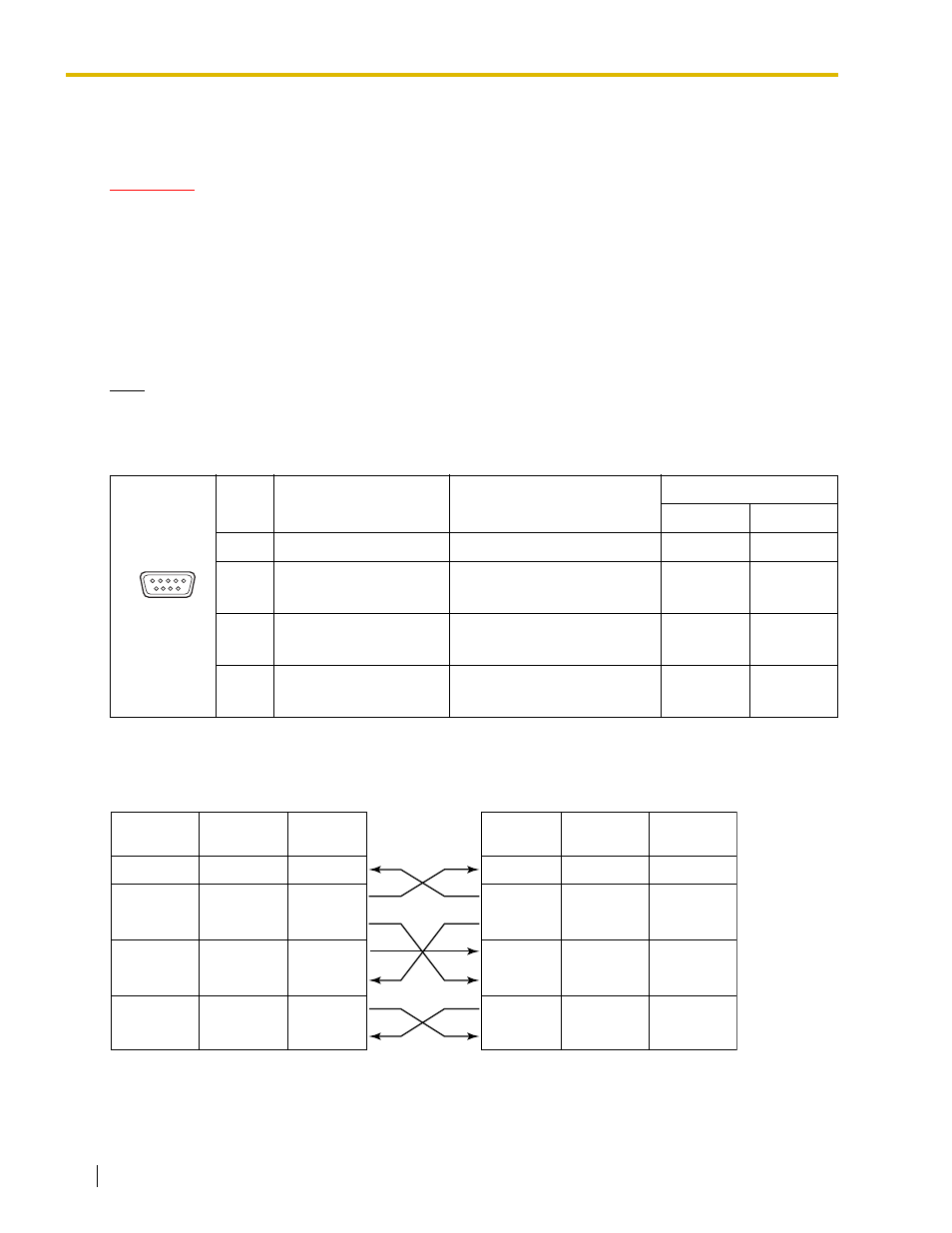
Use an RS-232C cross cable for connection between the PBX and PC.
Pin Assignments
Connection Charts
For connecting a printer/PC with a 9-pin RS-232C connector
No.
Signal Name
Function
Circuit Type
EIA
CCITT
2
RD (RXD)
Receive Data
BB
104
3
4
SD (TXD)
ER (DTR)
Transmit Data
Data Terminal Ready
BA
CD
103
108.2
5
6
SG
DR (DSR)
Signal Ground
Data Set Ready
AB
CC
102
107
7
8
RS (RTS)
CS (CTS)
Request To Send
Clear To Send
CA
CB
105
106
6 9
1 5
PBX
Printer/PC
Circuit Type
(EIA)
Signal
Name
Pin No.
Pin No.
Signal
Name
Circuit Type
(EIA)
BB
RD (RXD)
2
BA
SD (TXD)
3
CD
ER (DTR)
4
AB
SG
5
CC
DR (DSR)
6
CA
RS (RTS)
7
CB
CS (CTS)
8
2
RD (RXD)
BB
3
SD (TXD)
BA
4
ER (DTR)
CD
5
SG
AB
6
DR (DSR)
CC
7
RS (RTS)
CA
8
CS (CTS)
CB