Disassembly of parts – Philips CS-E15DB4EW User Manual
Page 72
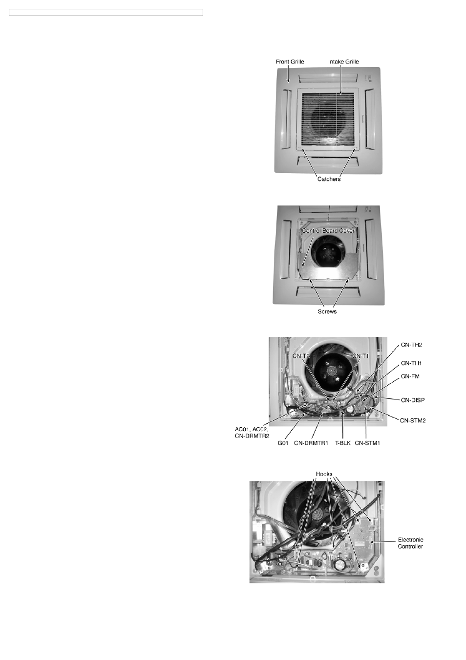
1. Open the Intake Grille from the Front Grille by moving the
catchers to center (Fig. 1).
2. Remove the Control Board Cover by removing the screws
(Fig. 2).
3. Release the (Fig. 3):
• CN-STM1 (WHT) connector.
• CN-STM2 (YLW) connector.
• CN-DISP (WHT) connector.
• CN-FM (WHT) connector.
• CN-TH1 (WHT) connector.
• CN-TH2 (BLU) connector.
• CN-DRMTR1 (BLU) connector.
• AC01 (BLK), AC02 (WHT) and CN-DRMTR2 (RED)
from Terminal Board.
• G01 (GRN) screw.
• Two T-BLK connectors.
• CN-T1 (WHT).
• CN-T2 (YLW).
4. To remove the Electronic Controller, release the 6 hooks
that hold it to the Control Board (Fig. 4).
Fig. 1
Fig. 2
Fig. 3
Fig. 4
12.5. Disassembly of Parts
72
CS-E15DB4EW CU-E15DBE / CS-E18DB4EW CU-E18DBE / CS-E21DB4ES CU-E21DBE