Connector tables, F-board connectors p-board connectors, F-board connectors – Panasonic GPH5D User Manual
Page 68: P-board connectors
69
Connector Tables
F-BOARD CONNECTORS
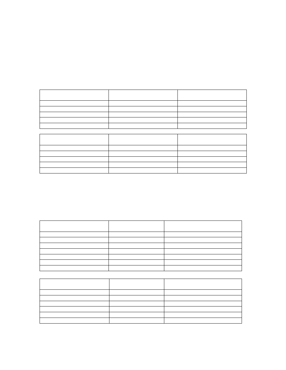
The following table lists the voltage levels present at each pin of the connectors
of the F-Board. Use this information to confirm that the F-Board is operating
properly.
Connector F1
Pin Numbers
Signal Name
Voltage Findings
1
AC IN
AC Line Input Level
2
NC
3
NC
4
NC
5
AC IN
AC Line input Level
Connector F9
Pin Numbers
Signal Name
Voltage Findings
1
AC OUT
AC Line input Level
2
NC
3
NC
4
NC
5
AC OUT
AC Line input Level
P-BOARD CONNECTORS
The following table lists the voltage levels present at each pin of the connectors
of the P1-Board. Use this information to confirm that the P1-Board is operating
properly.
Connector P1/SS1
Pin Numbers
Signal Name
Signal Flow
(Board or Connector)
1
NC
P1---
àSS1 (SS-BOARD)
2
VSUS
P1---
àSS1 (SS-BOARD)
3
VSUS
P1---
àSS1 (SS-BOARD)
4
NC
P1---
àSS1 (SS-BOARD)
5
GNDa
P1---
àSS1 (SS-BOARD)
6
GNDa
P1---
àSS1 (SS-BOARD)
7
GNDa
P1---
àSS1 (SS-BOARD)
Connector P2/SC2
Pin Numbers
Signal Name
Signal Flow
(Board or Connector)
1
VSUS
P2---
àSC2 (SC-BOARD)
2
VSUS
P2---
àSC2 (SC-BOARD)
3
NC
P2---
àSC2 (SC-BOARD)
4
GNDa
P2---
àSC2 (SC-BOARD)
5
GNDa
P2---
àSC2 (SC-BOARD)
6
GNDa
P2---
àSC2 (SC-BOARD)