Panasonic GPH5D User Manual
Page 11
12
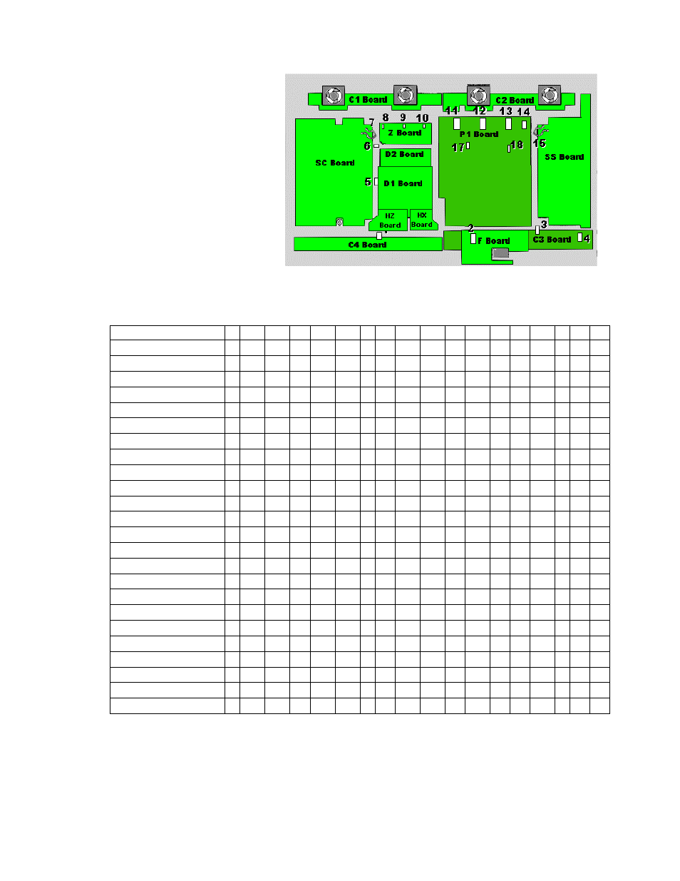
Location of Lead Wiring
High frequency
electromagnetic signals can
create electrical interference
within the unit. Be sure to
route all wires through their
respective harnesses
reference.
The chart below is an
illustration representing the
connectors and the wire
harnesses associated
with them.
Harness Number
Connector Number
1
2
3
4
5
6
7 8
9
10 11 12 13 14 15 16 17 18
Z6
è P6
Œ
Z10
è D10
Œ Œ
Z17
è D17
• Œ
D12
èD22
D16
è D26
D25
è P5
Œ Œ Œ Œ
D27
è P7
Œ Œ Œ Œ
SC2
è P2
Œ Ž Œ Œ Œ Œ Œ
SC4
è P4
Œ Ž Œ Œ Œ Œ Œ
SC20
è D20
Œ
SC21
è D21
Œ
H37
è Z3
Œ
Œ Œ Œ Œ
Œ
H37
èZ4
Œ Œ Œ Œ Œ Œ Œ Œ Œ
Œ
SS1
èP1
•
SS3
èP3
Œ
SS32
èC32
SS42
èC42
Œ
ESC POWER
è SS34
Œ
ESC V-BOARD
è C44
Œ
F9
è P9
Fan 1
è P10
Œ Ž Œ
Fan 2
è P11
• • Œ
Fan 3
è P12
Œ Œ • •
Fan 4
è P13
Œ Œ Œ •
Π= Wind the cable through the clamper once
• = Wind the cable through the clamper two times
Ž = Wind the cable through the clamper three times
Clamper Locations
Figure 9